Autonomous Delta Wing
A small delta wing UAV capable of autonomous flight based on the PX4 flight stack.
Introduction
When I first started getting interested in UAVs, I pursued building multirotors. Multirotors have the capability of hovering; this low speed state is a great place to start learning for an inexperienced pilot. The main disadvantage in starting with multirotors is that the richness of attitude control for an innately unstable, underactuated vehicle is usually abstracted away. When beginning to bring new UAVs@Berkeley club members up to speed on quadcopter dynamics, they are often surprised to hear that we can’t simply set the 4 motors to produce enough thrust to counteract gravity and expect to hover. Wings, on the other hand, have some minimum required forward velocity before they’re able to maintain level flight, but they can be designed to be attitude stable and don’t necessarily require any onboard control loop for a hobbyist to have fun. Compared to a multirotor, wings can also be much faster in forward flight and far more power efficient. Delta wing configurations in particular have a very low drag coefficient and very few actuators (usually just a motor for thrust and two servos for the left and right elevons - a portmanteau of the words “aileron” and “elevator” because elevons combine the functions of ailerons and elevators). Elevons simply deflect in opposite directions to create a roll moment on the aircraft, and deflect in unison to create a pitch moment.
I wanted to get involved in wings in some capacity, so I decided to purchased a used RC delta wing about a year ago. I immediately crashed it (in part due to an uncalibrated center of gravity, but definitely due to pilot error), and that’s where part one of this post starts, repairing the broken wing. Part two involves the construction of a brand new wing capable of fully autonomous flight.
Part 1
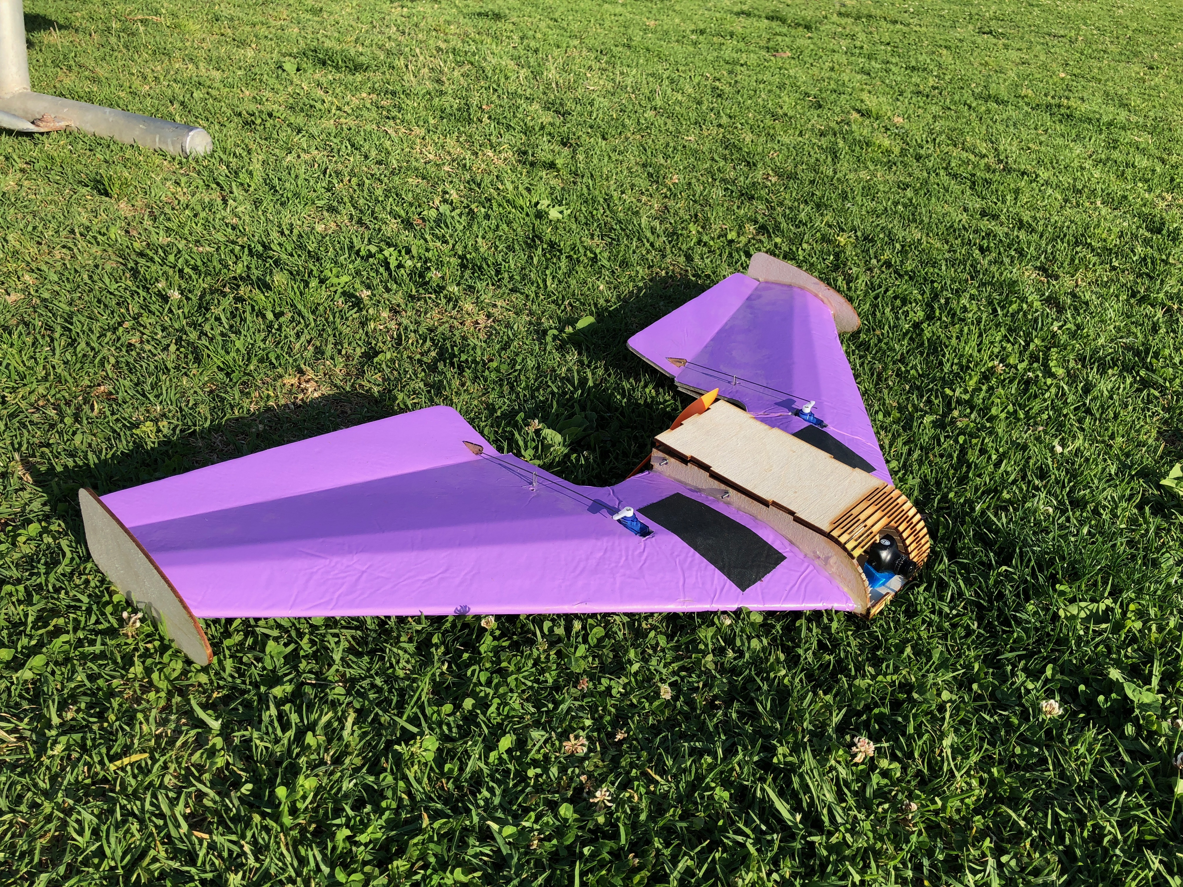
Below is the delta wing I purchased, it’s made from a Flite Test Arrow airframe and various off the shelf electronics. It was equipped with a live first-person-view (FPV) analog video feed transmitted over 5.8Ghz and a FrSky frequency hopping receiver at 2.4Ghz. This vehicle had no flight controller onboard, the receiver was connected straight to the servos and electronic speed controller. That means I was in full control of the vehicle with the sticks on my transmitter correlating to angular velocity about each axis.
Given my experience with racing quadcopters, I expected to at least be able to bring the plane safely back to the ground after I launched it. During the maiden flight I crashed it and destroyed the center pod. Thankfully, no electronics took any damage, and the wings maintained their integrity. I removed all the undamaged components from the wreckage and disposed of the center pod. I left the field that day humbled, but at least I had the opportunity to be creative with my repairs.
Center Pod Design
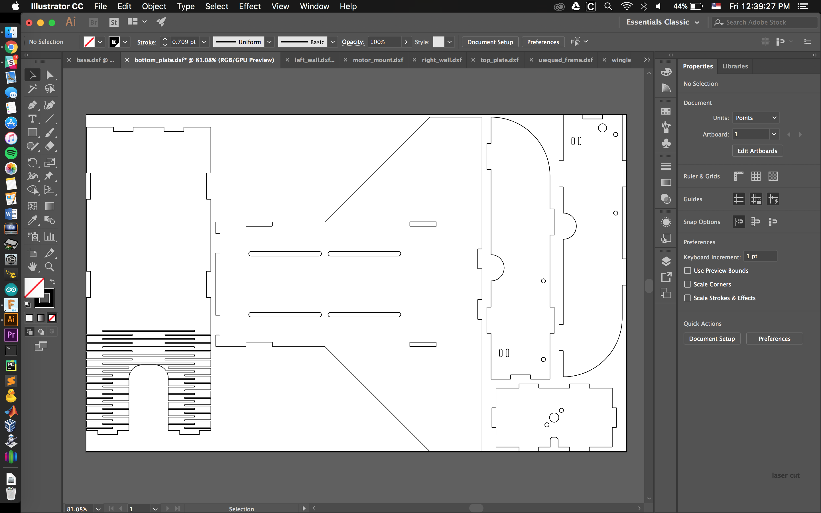
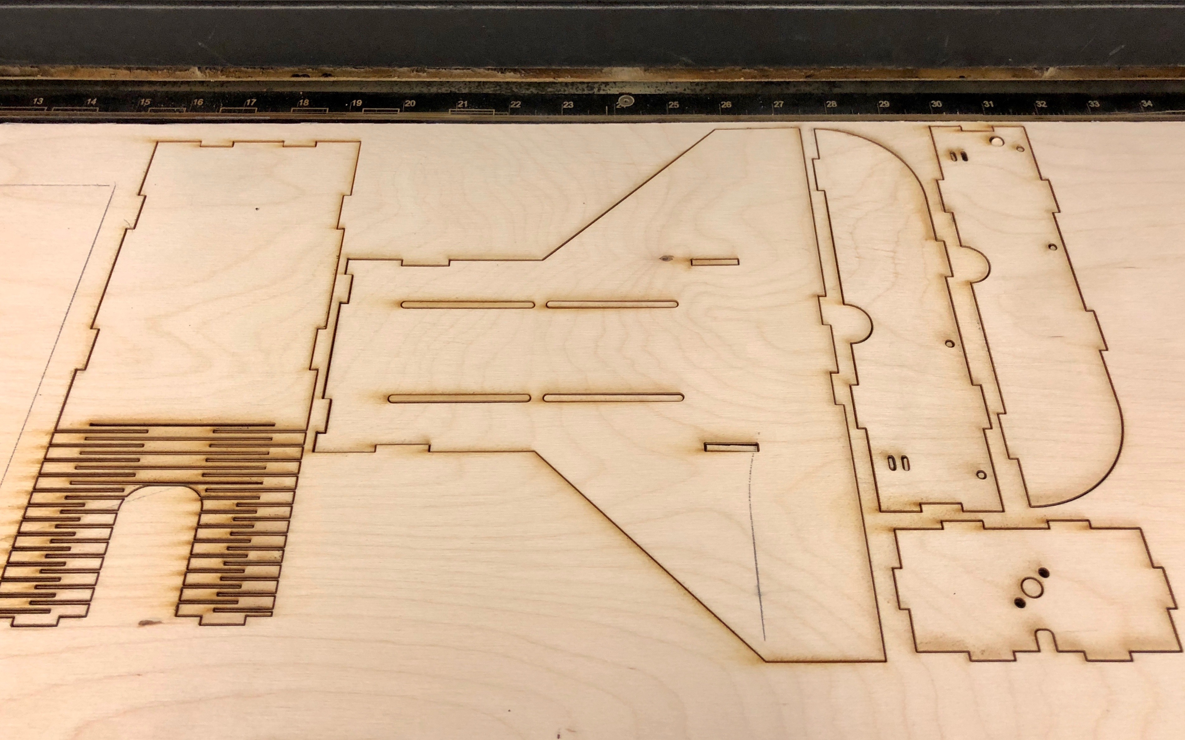
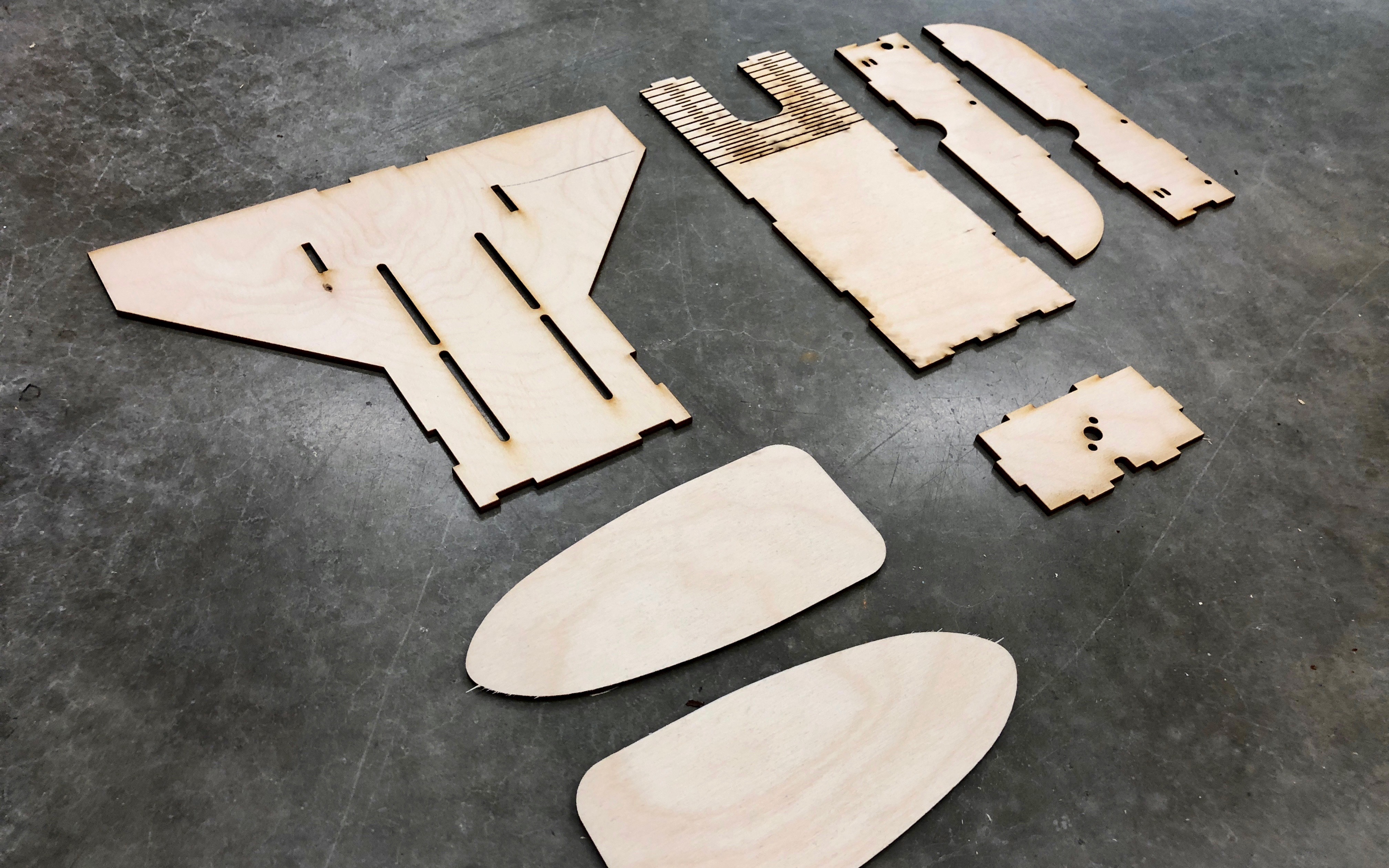
The standard Flite Test airframe is made out of folded foam board held together with hot glue. I decided to increase my chances of surviving a few more crashes in the next iteration of the build by replacing the center pod with laser-cut 1/8th-inch thick plywood. I designed the center pod to be wider than the stock version to improve serviceability and leave room for a flight controller in the future. The new pod consists of a top plate that extends to the nose, two side panels with mounting holes for antenna and M3 hardware, a bottom plate with slots for velcro-strapping a battery, and a back plate with mounting holes for a brushless motor. All the pieces would be secured together along their edges with tongue joints and wood glue. I designed the new pod in Autodesk’s Fusion 360 CAD tool, then exported a DXF to Adobe Illustrator for laser cutting. Below is the design file in Illustrator, the parts cut on the bed of the laser cutter, and the cleaned up parts ready for gluing. The original winglets for the wing were damaged in the crash, so I designed and cut some new ones from the same material.
Kerfed Nose
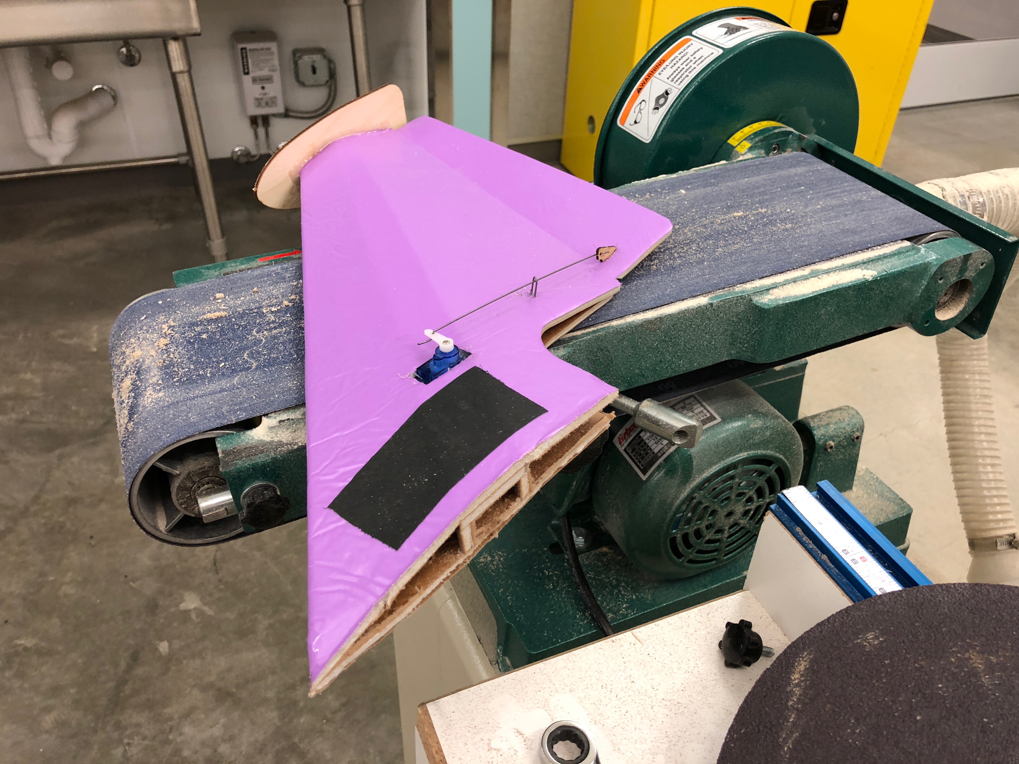
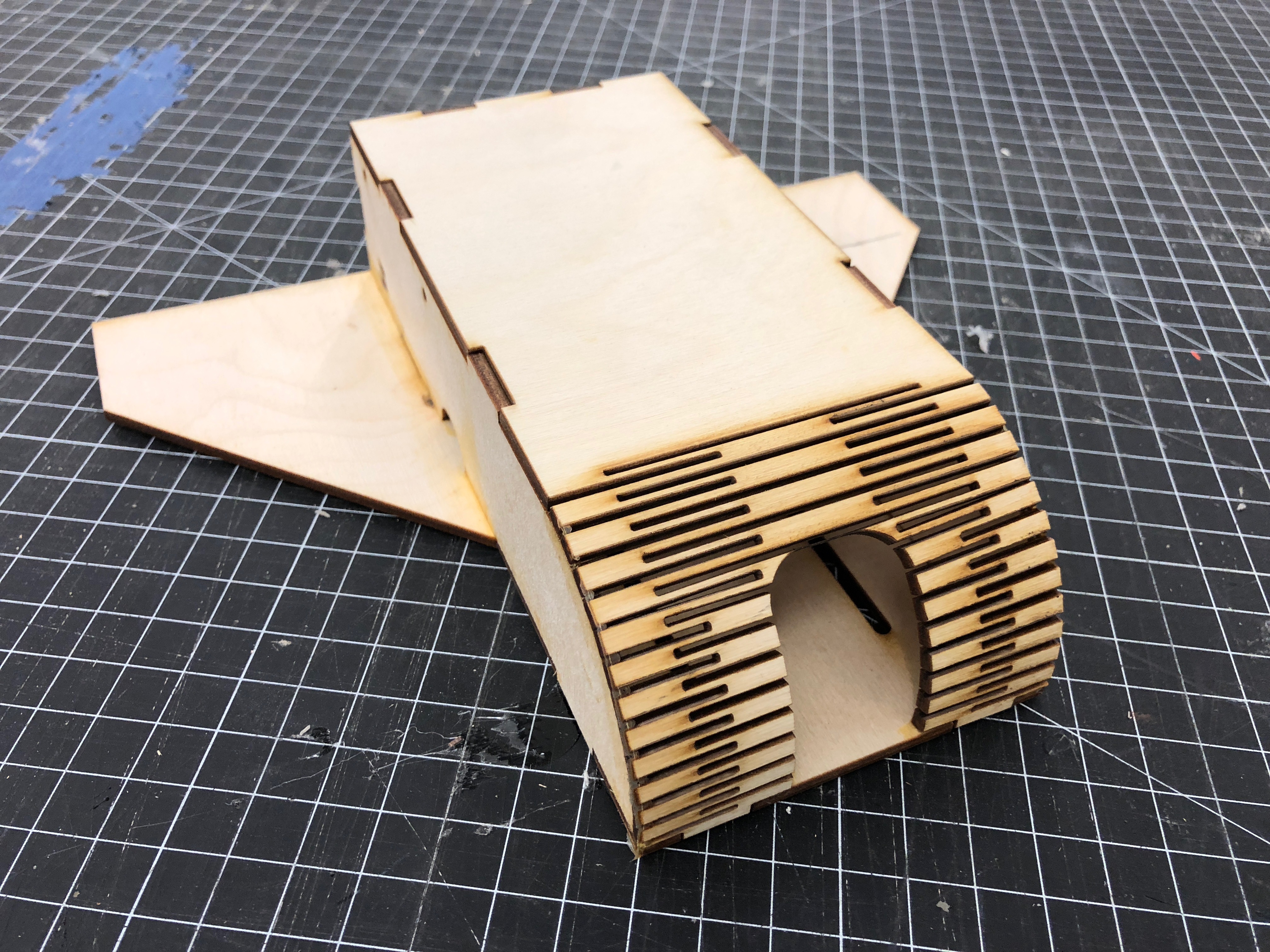
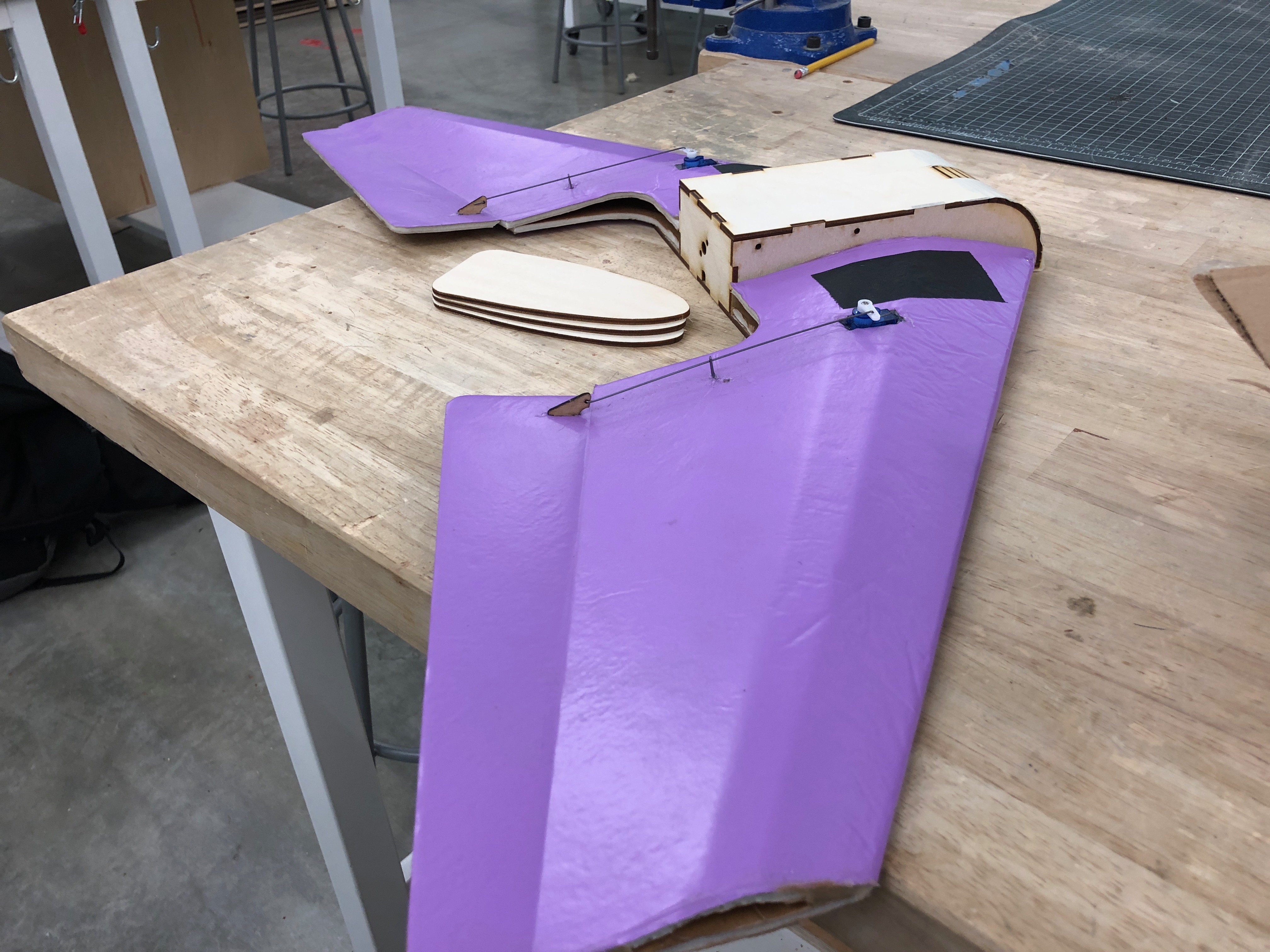
A popular wood working technique for bending wood is called “kerfing.” Essentially one makes many small parallel cuts to allow the wood to become a shapable, living hinge. This technique becomes extremely easy to execute with accuracy when a laser-cutter is available. I included a kerfed edge along the nose of the center pod I designed to give the front-end a rounded edge similar to the stock design. The kerfed section also serves as a living hinge to open the top of the pod for battery replacement or access to the electronics. There’s a horseshoe-shaped gap towards the bottom of the kerfed section for an FPV camera to have a front facing view, but remain protected from head-on impacts. I can’t speak to the aerodynamics of the nose of the aircraft, but I was very happy with the aesthetics and hinge functionality. Below is one of the repaired wings which needed some slight modifications on the belt sander, the glued center pod ready for install, and the wings secured to the new center pod on the work bench.
Flight Test
I didn’t get the chance to actually test fly the repaired vehicle for about six months. Once I finally did, I was much more careful to achieve the correct center of gravity. Center of gravity, and it’s position relative to the center of lift plays an important role in the flight characteristics of any plane, but it is especially critical in flying wings due to the lack of a tail. The center of lift is a function of the wing geometry, defined by the manufacturer from testing or computational fluid dynamics (CFD) simulations. Manufacturers of model aircraft frames will usually define an acceptable range for the center of gravity based on where the center of lift falls for the vehicle. For me, the CoG was in front of the CoL (a slightly nose-heavy configuration), providing passive pitch stability. Below is the final pre-flight state of the repaired wing, electronics installed and ready for round two.
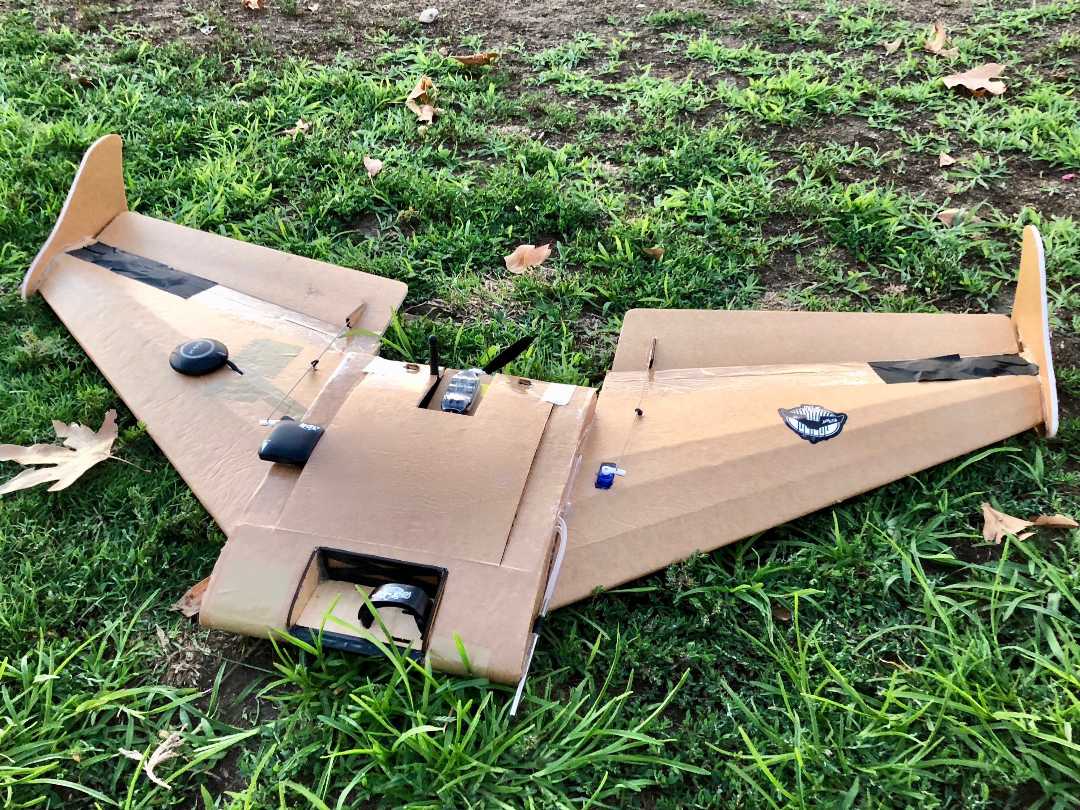
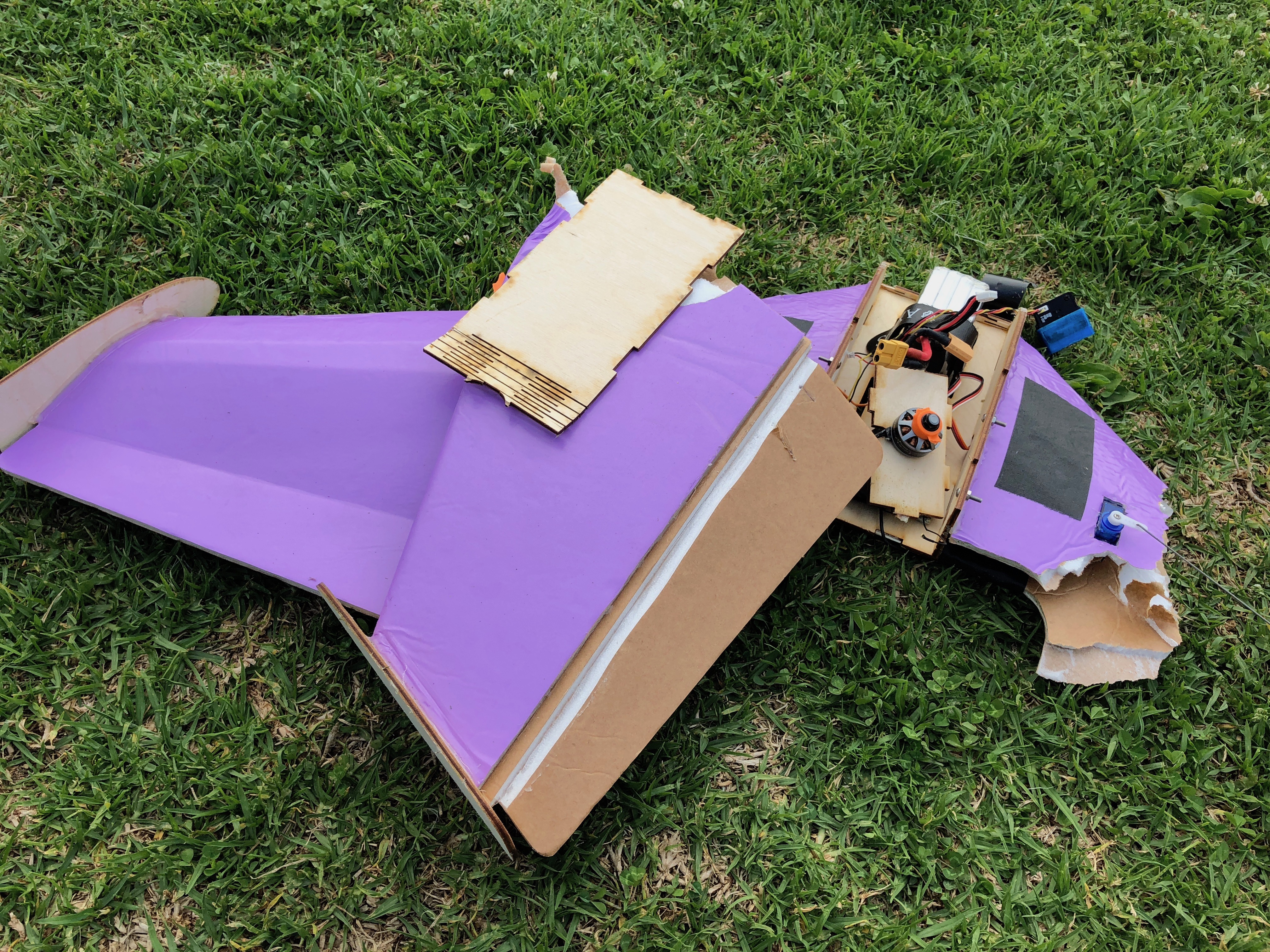
I performed my first successful hand launch of a plane with this vehicle and successfully flew a few batteries worth laps around a local field via line-of-sight. I was by no means relaxed during my first few flights, but the wing performed well once I had trimmed the control surfaces and got comfortable with the nonexistent yaw authority. A few batteries in, I decided to try some low altitude, high speed passes. You guessed it, I put right into a tree at about 40mph. Below is the state of wing after about an hour of enjoying it.
Armed with the knowledge that I’m not a particularly talented RC plane pilot, I decided the next build would be constructed from similarly low cost materials, but would also include a sensor suite and onboard flight controller allowing me to fly in assisted flight modes, as well as run completely autonomous missions.
Part 2
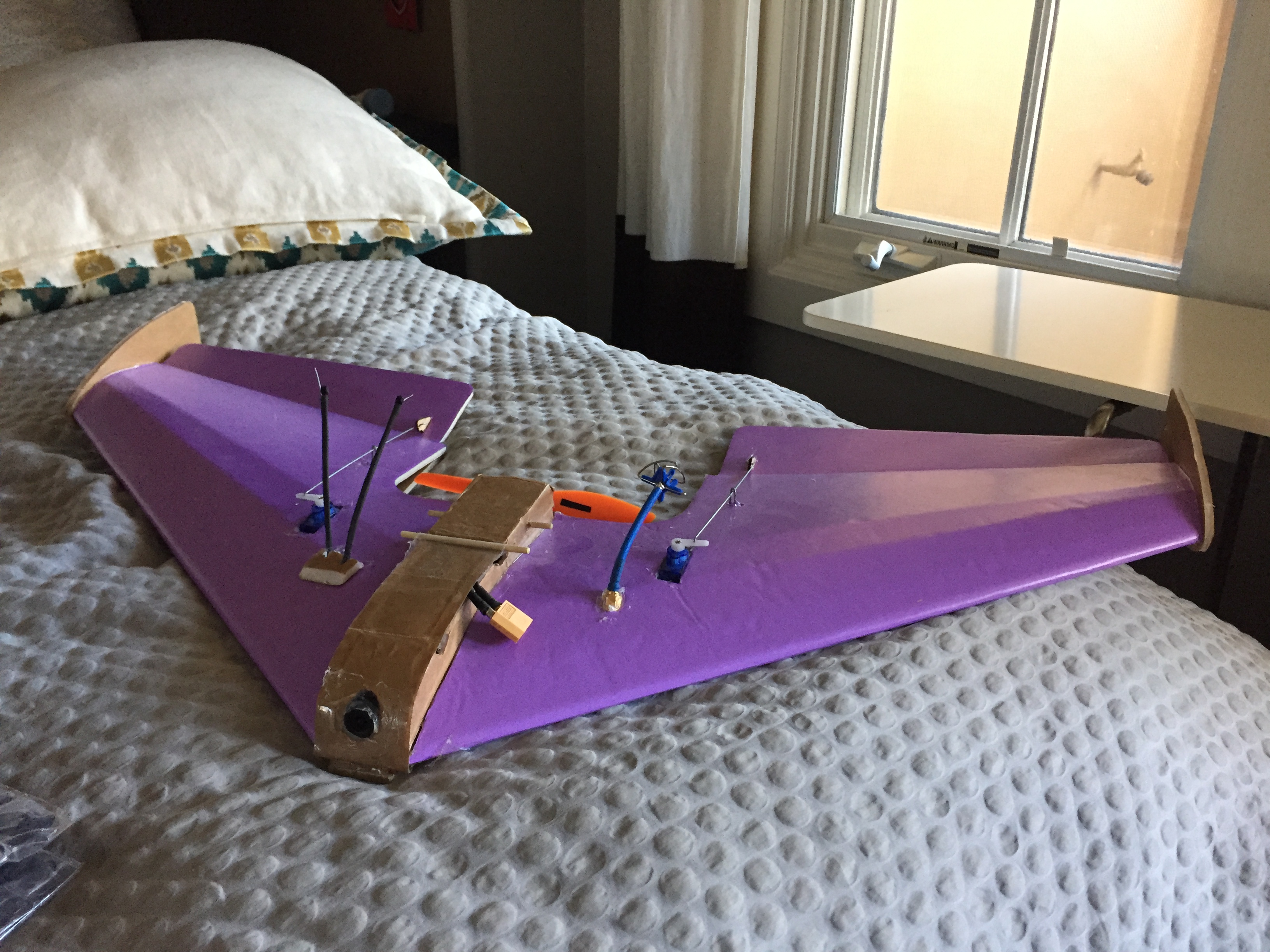
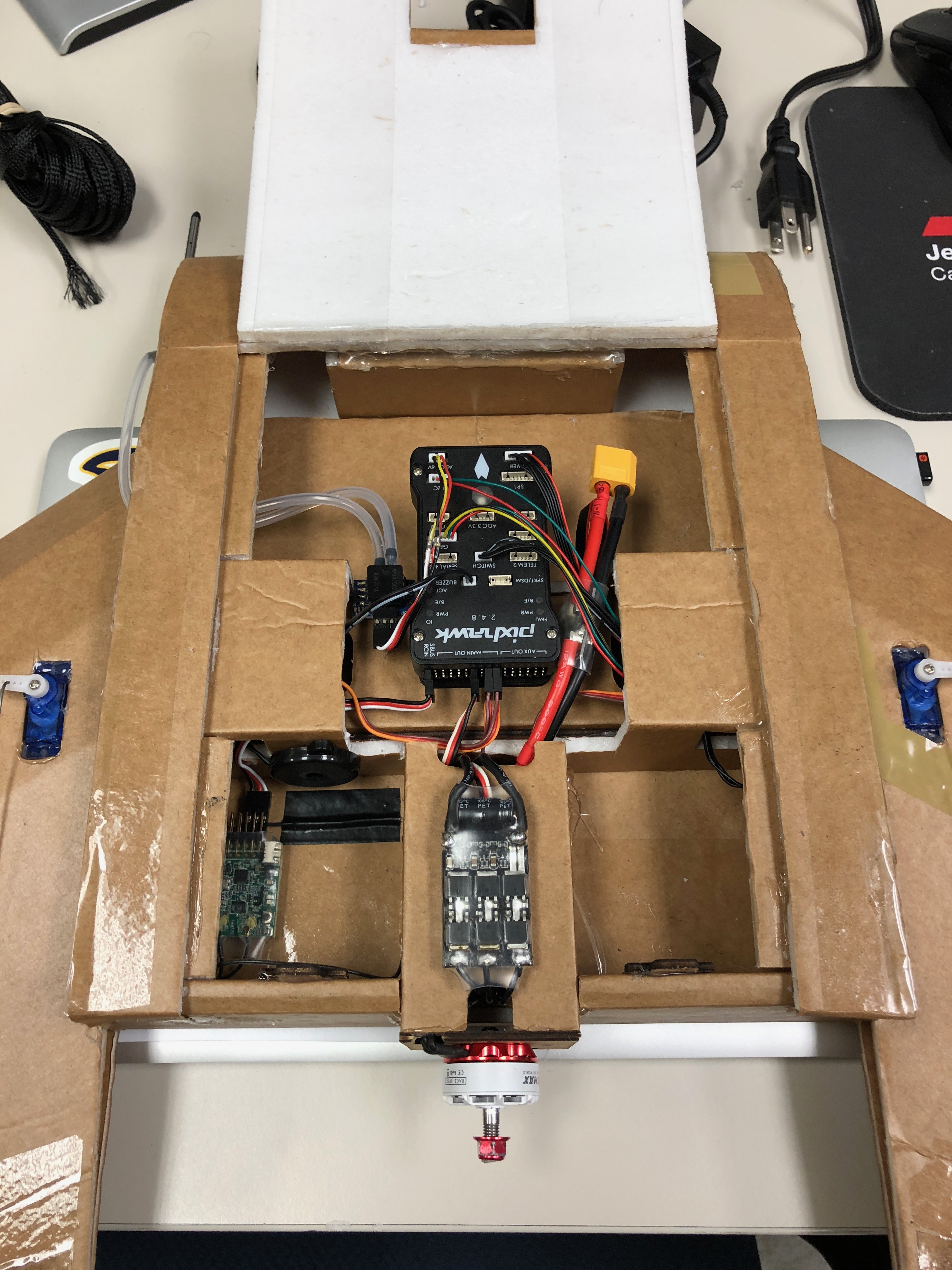
Another six months passed, another semester came to a close, and finally I had the time to get to work on a new plane. This one was built from a Flite Test Spear foam board airframe. It is a very similar geometry to the Arrow used in the first build but has a massive payload bay for storing extra batteries, a GoPro, a flight controller, more sensors, etc. The airframe only took a two or three hours to fold into shape and cost about $40 USD. I transplanted the receiver, servos, and ESC from the original build then set about integrating new flight control hardware which was mostly sourced from mRobotics. mRobotics is a relatively new spinoff from some of the hardware designers who were working at 3D Robotics during their development of the original Pixhawk flight controller. Below is a rough bill of materials for the vehicle along with a shot of the completed payload bay.
Bill of Materials
| Item | Description |
|---|---|
| LiPo battery | 4S 1500mAh pack for power with an XT60 connector |
| Brushless Motor | An EMAX 2306 2300KV motor designed for racing multirotors in a pusher configuration for thurst |
| Electronic Speed Controller | A 40A ESC with a 5V battery eliminator circuit for speed control of the motor |
| Propeller | 6x4.5 two-bladed propeller made from glass-nylon |
| Servos | 9g hobby servos glued into the wings to actuate the elevon control surfaces |
| Flight Controller | A Pixhawk FMUv2 with an included IMU built around a 32-bit ARM Cortex M4 processor |
| Receiver | FrSky frequency-hopping spread spectrum 2.4Ghz control receiver for manual flight input |
| Pixhawk Power Module | A small module in series with the battery that includes voltage and current sensing circuits for telemetry |
| Airspeed Sensor | An mRo airspeed sensor which communicates of I2C connected to a front facing pitot tube |
| GPS | mRo GPS module with a u-Blox Neo-M8N and included compass for 3D localization tuned for GPS and GLONASS networks |
| Telemetry Radios | mRo 915Mhz SiK telemetry radios for two-way telemetry downlink and command upload from the ground control station |
PX4 Flight Stack
I’ve used variants of the PX4 open source flight control firmware before, but only for multirotors. I read through the PX4 User Guide as well as the Dev Guide in order to better understand the important differences between the vehicle architectures. Aside from the low level controllers, mixers, and flight modes, there are few differences between the fixed-wing and multirotor workflows.
Now we can get into the good stuff: below is a block diagram for PX4’s stock fixed-wing attitude controller pulled from the dev guide. It’s a proportional attitude controller which cascades into a PI angular rates controller. The output of the controller is the desired angular acceleration, which is then translated into control surface servo position based on a priori knowledge of the vehicle - moments of inertia, area of the control surfaces, etc. These parameters can be collected from CAD or from manual test flights where the controller is turned off.
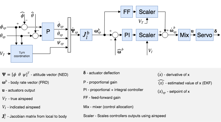
Some points of interest on this controller: the scaler block which appears after the PI angular rates controller is a function of indicated airspeed. This is to account for the increase in control authority with increasing airspeed. Conversely, the control gains should be boosted at low airspeeds to achieve the same angular accelerations about each axis.
Also, there’s a feedforward term that appears near the top of the diagram. This shows up to account for “aerodynamic damping.” This is a force experienced by a fixed wing aircraft, proportional to the angular rate about an axis, which resists that rotation. If you imagine pulling continuous barrel rolls in a delta wing aircraft, it’s intuitive that there’s some extra drag associated with churning the wings through the oncoming air. The feedforward term in the controller fights that damping effect.
Autonomous Flight
Here’s the completed wing after my first few test flights (you’ll notice its still in one piece).
After confirming the manual and automated control outputs deflected the elevons correctly, I flipped the flight mode to “stabilize.” This is an assisted flight mode where the controller abstracts angular rates away from the pilot, so the sticks on my transmitter correlated with pitch and roll angles. I boosted the wing up to 75% throttle and had my friend Rohan give the wing a toss. We went for the maiden flight without tuning the controller, or providing any vehicle-specific parameters to PX4 aside from the “generic delta wing” designation. The controller performed surprisingly well, there were some minor roll-axis oscillations that could be tuned out easily by creating a vehicle type specific to this wing’s geometry. After I was confident enough in the flight worthiness of the plane, I strapped my GoPro on to get some flight footage, below is a quick edit with some first person and third person views of early flights.
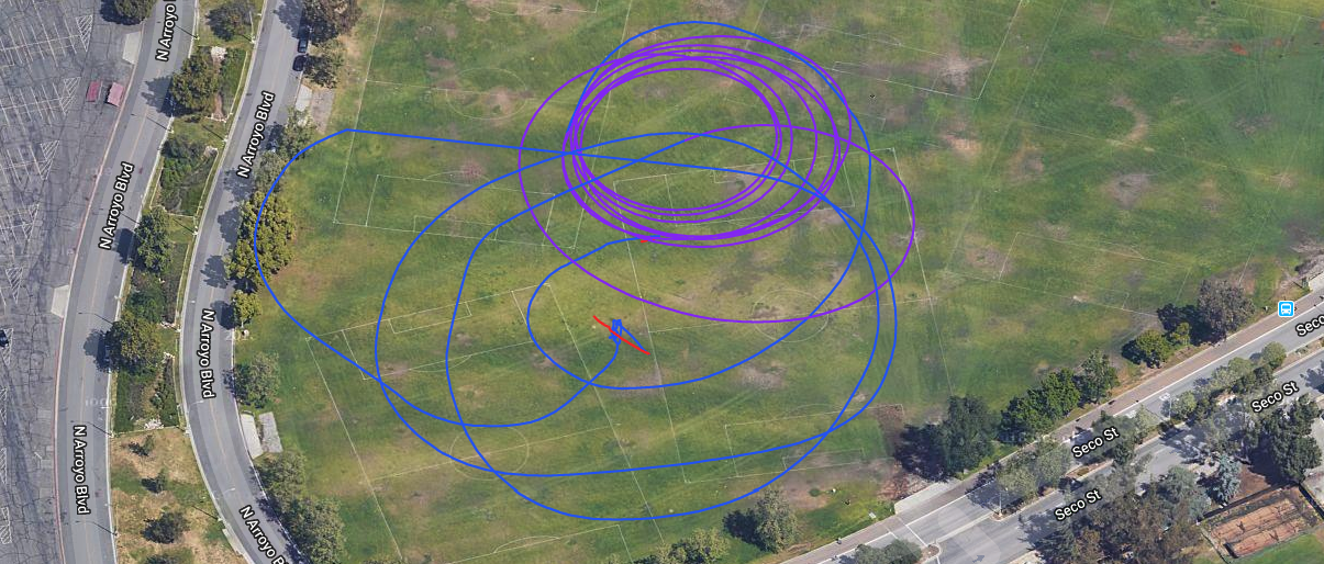
Before the end of the day, I felt comfortable transitioning from assisted flight modes to full autonomy. I added the “loiter” flight mode to a switch on my transmitter, where the plane simply circles around a GPS waypoint at a radius and altitude configurable in the ground control station software on my laptop (I used QGroundControl). The flight consisted of a hand launch in stabilize mode followed by a few laps, then a switch to loiter, then a switch back to stabilize mode for a landing. The results are below, the entire flight path is projected onto the ground with blue the stabilized flight path and purple the fully autonomous loiter.
Telemetry Analysis
My favorite part of this dive into the vanilla PX4 code base was the absolutely beautiful telemetry log viewer, its called Flight Review. Here is a sample of the interface with my actual flight data. It’s a completely web-based interface with a dead simple UI. You simply upload a log file saved to the Pixhawk’s SD card for each flight and it displays the pertinent data in an intuitive and interactive way. There’s even built-in support for a full 3D renders of flight trajectory via Cesium, including real time playback. Click here to check out a Cesium render of one of my autonomous test flights performing a circular loiter at 50m in altitude at a 30m radius.
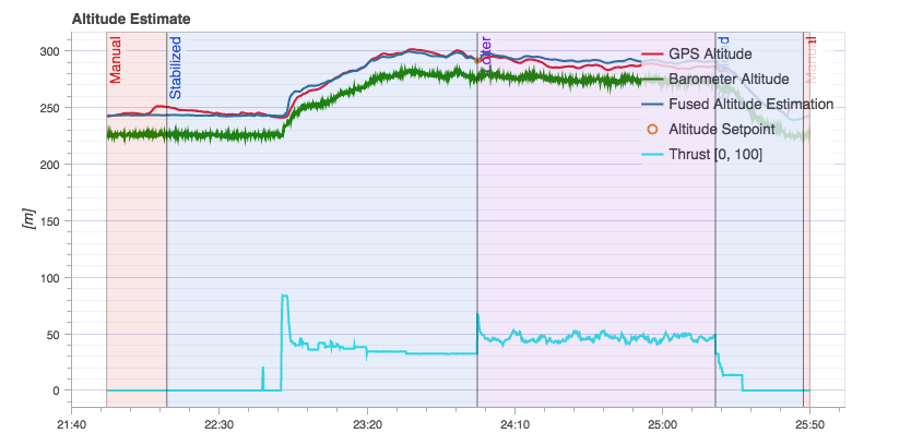
GPS altitude, barometer data, and IMU measurements contribute to the altitude estimate fused via an EKF. Below is one of the more interesting plots which shows the varying levels of noise inherent in each sensor.
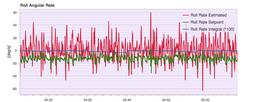
I mentioned earlier that I noticed some roll oscillations throughout the flight tests, sure enough you can see the roll estimate overshooting its setpoint continuously. Definitely room for improving upon the tuning from stock.
Next up in my fixed-wing UAV shenanigans: I’d like to build a long range vehicle with much more robust radio links and greater endurance, potentially from higher quality airframe materials. There’s a lot to be done in terms of waypoint navigation and autonomous missions. Even longer term, I would love to build up a telemetry connection to a remote vehicle over LTE. Being able to remotely monitor telemetry and upload new waypoints, regardless of my distance to the vehicle, would be an incredible capability.