Waterproof Quadcopter Build
A waterproof quadcopter built around the crazyflie flight controller for a professor researching aquatic drone launches.
Introduction
After taking “Intro to Control for UAVs” (ME136) in the Fall of 2017, the professor, Mark Mueller, recruited my lab team (my good friends David and Joey, and myself) to design and build a quadcopter to be used in his lab for research purposes. One of his graduate students is working on launching a drone from the ocean. This platform will be a test rig to be used within the lab as the grad student works on modeling the dynamics of an aquatic launch and developing control systems to achieve this reliably.
This effort did ultimately lead to conference paper published in the proceedings of the 2019 International Conference on Unmanned Aircraft Systems (ICUAS). The paper, authored by my HiPeRLab colleague Jiaming Zha, is entitled “Towards breaching a still water surface with a miniature unmanned aerial underwater vehicle” and is available here.
Requirements
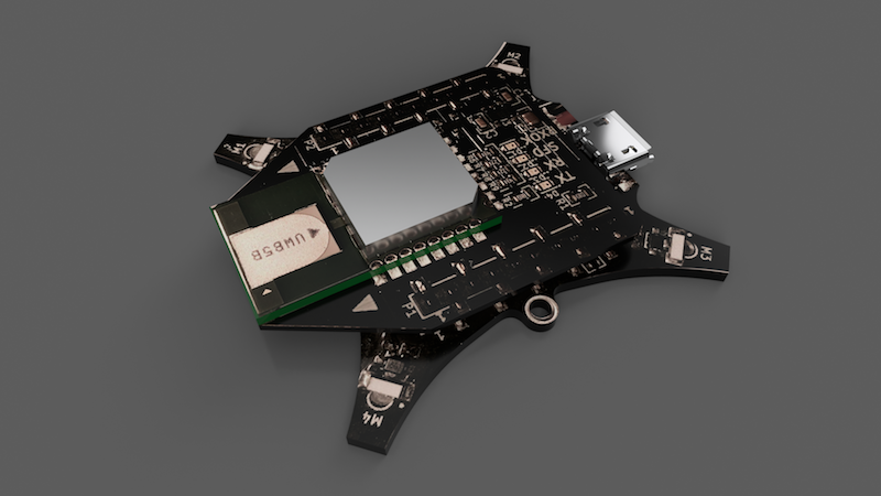
The build had to employ the same flight controller that the lab already used for their other drone related projects, the Crazyflie from Bitcraze, a PCB designed to drive brushed motors.
- Run the Crazyflie flight control board (an STM F4 microcontroller)
- Have enough room for a radio based localization unit used for state estimation
- Limit voltage to a 2S LiPo's 8.4V
- Must be compact, less than 200mm motor shaft to motor shaft
- Must be agile, at least a 2:1 thrust to weight ratio
- Operate down to 3m of depth
- Full battery voltage telemetry
Component Specification
Systems engineering for a multirotor is a large optimization problem including factors such as motor stator size, motor KV, prop diameter and airfoil, battery voltage and capacity, and aircraft size, weight, and configuration. Thankfully the requirements for the platform narrowed down our choices.
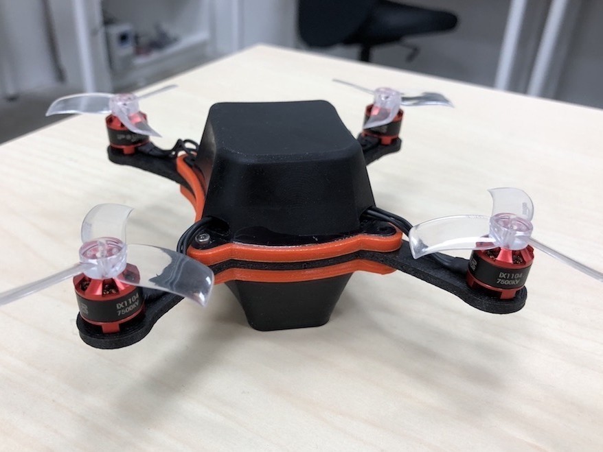
We estimated we could meet all the requirements with a craft weighing around 100g. Based on existing motor thrust testing, we found that an 1104 7500KV motor could achieve 100g thrust on 2S running a 2-inch prop, so we’d achieve a power to weight ratio of roughly 4:1.
With this, we decided on a 2S LiPo at 400mAh. Knowing that all our components would have to be submersible, we decided to look around 10A rated 4-in-1 ESCs (4 ESCs for brushless motors on one PCB for easy mounting inside a waterproof enclosure).
With our powertrain specified, we found the proper components on Amazon and began recreating them in CAD so I could design our frame and waterproof enclosure around them. The Bill of Materials for off the shelf components we included in the build is as follows:
Bill of Materials
| Item | Description | Total Weight Contribution (grams) |
|---|---|---|
| Crazyflie Flight Controller | STM F4 based microcontroller with an IMU and several UARTs | 7 |
| Bitcraze Loco Positioning Deck | RF based localization module | 3.3 |
| iPower iX1104 7500KV Brushless Motor | Brushless motors | 22 |
| Wave 4-in-1 10A ESC | Single PCB with 4 ESCs for brushless motors rated for 10A continuous | 6 |
| Crazepony 400mAh 2S 7.4V 30C LiPo | A small 2-cell LiPo | 22 |
| Gemfan 2040 Tri-blade Props | Some 2 inch diameter tri-blade propellers | 3.6 |
| Matek Systems Micro BEC 5V/12V Adjustable Buck Module | Battery eliminator, a 5V bucking regulator | 1 |
Design
The main design constraint was the requirement that the vehicle must be submersible. Brushless motors are waterproof out of the box due to the insulating enamel applied to the wires of the motor winding in the stator, they can operate underwater without modification. Everything else (flight controller, ESCs, localization module, voltage regulator, battery) had to somehow be waterproofed or inside a watertight container.
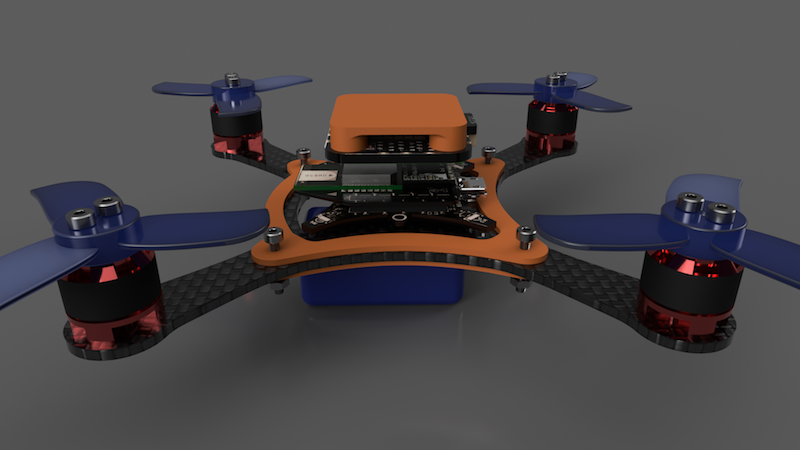
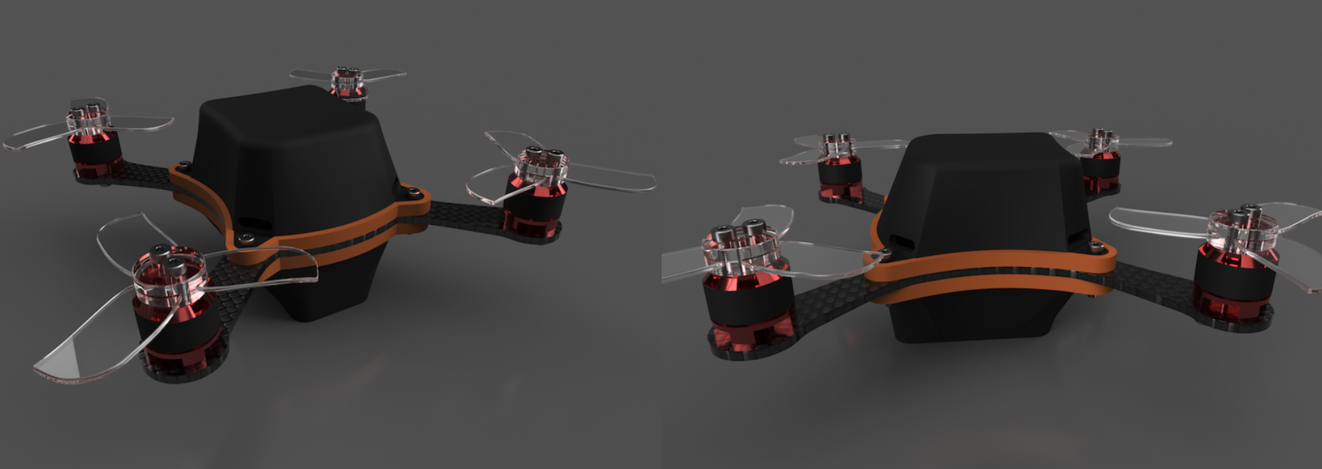
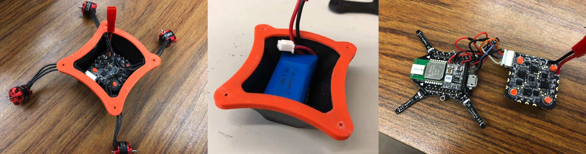
David, Joey, and I brainstormed on how we might protect the sensitive PCBs from the elements within a container. For the sake of preserving an ideal center of mass, close to the geometric center of the vehicle, we decided on two cases which sandwich the frame of the quadcopter. The top case contains all the sensitive PCBs and the battery is protected by the bottom case. A hole is cut in the frame for the battery lead to reach the ESCs and regulator in the top case. 20+ hours of CADing in Fusion 360 later, I completed the full vehicle assembly including a custom frame, top and bottom cases, as well as gaskets to seal the cases against the frame. I included every single PCB as each would be mounted in the case and designed the cases around the components. This ensured a reasonable fit as well as the accuracy of the inertia tensor of the vehicle, an input to the PX4 firmware the lab had running on board the Crazyflies for flight control.
The electronics are mounted inside the top case using TPE mounting solutions, CA glue, heavy duty double sided foam tape, and M2 fasteners. There are 4 holes in the top case which allow the motor wires to reach the ESC board inside the case. Those holes would be filled with a rubbery silicon caulking with the wires threaded through.
Fabrication
Watertight Cases
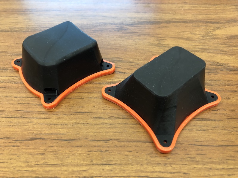
3D printing was the natural choice for fabrication of the custom cases, but normal FDM prints are not watertight. Small gaps between layers can allow some water to permeate even a thick shell of typical 3D printing plastics. SLA type prints (laser/projection based resin curing processes) are bound at a molecular level, so those are watertight. Thankfully at Jacobs Hall on campus at UC Berkeley, we had access to a Carbon3D printer for fabrication of the cases. I had never printed anything with an SLA printer before, it was definitely a learning curve. This printing process has its own intricacies and there are different issues to debug than I was used to on FDM machines. It took 3 or 4 iterations before I established how to avoid vacuum pockets forming in the print, and how to arrange the support structure to avoid warping. Once I was happy with the part and its fabrication, I printed a top and bottom case in black “rigid polyurethane” on the Carbon 3D. All the Carbon3D resin chemistries are proprietary so beyond “polyurethane,” I really have no idea what the parts are made of. They were durable though and worked beautifully.
TPE Gaskets
The weakness of our double case sandwich approach is the potential leak at the interface between the cases and the frame. We had seen rubber gaskets used in other systems at an interface which needed to be watertight. A flexible 3D printing filament called thermal polyurethane (TPE) came to mind. I designed some gaskets which fit along the footprint of the top and bottom case along the frame. They are meant to be compressed when the top and bottom plate sandwich the frame using a few M2 nuts and bolts. I printed the gaskets in orange NinjaFlex TPE on my personal Printrbot Simple and over-extruded the prints severely to ensure better-than-average layer adhesion. The gaskets would be adhered to the cases with CA glue with the exposed interface between the case and gasket covered in watertight silicon conformal coating.
Frame
Ideally, the custom frame would be cut from a 3mm thick plate of carbon fiber. It would be rigid, light weight, and durable. We had the carbon purchased, but unfortunately, we were finishing this project towards the end of the semester. During the last week of class, the waterjet we needed to access to safely CNC cut the carbon was booked due to other class projects being due for many other students. Cutting the carbon on a typical CNC mill would be a hard sell to the machine shop technicians as carbon fiber dust is one of the last things you’d like in your lungs. 3D printing to the rescue again… we recruited our good friend Eric to complete a specialty print for us. Eric owns a printer with several upgrades allowing him to print abrasive and high-temperature filaments. He printed us a frame out of carbon-reinforced nylon, an extremely durable material. It’s not as clean as the carbon fiber plate we planned on, but it’s rigid enough to be flight worthy.
Assembly and Delivery
After removing excess pins, direct soldering all the components together, and installing a voltage divider for stepping down the input to the VBAT sensor, we covered all the electronics in 2 coats of silicon conformal coating for safety in the off chance that any moisture got inside the case.
Modification to the PX4 firmware running on the Crazyflie is necessary for the PWM signal output to the ESC to be read correctly, and thus appropriately control the motors. PWM signal timing was adjusted to the standard 1000-2000 microsecond period, but the logic level of the signal worked out of the box. We also changed a hard-coded scaling factor to read the correct battery voltage from our new VBAT sensing resistor values.