Custom Electric Longboard
A custom electric longboard and handheld wireless controller.
Motivation
I go to school in Berkeley, CA. The campus is built on a hill, so it’s difficult to get from point A to point B if point B is East of point A. Electric vehicles are, of course, the future of personal transportation, but I’m on a budget so a Tesla isn’t an option. In fact, even a $1,400 Boosted Board is a little pricey. I decided to build my own electric longboard to get around the Berkeley hills, I wanted all the torque I could muster whilst keeping the cost down.
Powertrain Specification
I knew I wanted to use two 4S LiPos in series to run my powertrain on 8S power because I can still use 4S batteries for other projects (flying drones, field charging other LiPos, etc.). With 8S voltage decided, what KV motor should I buy and what gear reduction should take place between the motor and the wheels?
Beyond the hills being hard to conquer, the pavement in Berkeley is treacherous. Big wheels make clearing gaps and cracks in the asphalt easier and the largest, easily found longboard wheels are 90mm in diameter. I do value my physical safety, so I decided on a top speed of 20mph. Upon doing some research, I found gear reductions on electric longboards to be anywhere from 1.8 to 2.5, I went with a 3:1 gear reduction to optimize for torque rather than top speed. We do some math to find the required motor KV:
- Desired top speed:
- Batrtery: 8S at (average voltage)
- Wheels: diameter
- Wheel circumference:
At a velocity of 8.89m/s where the wheels roll 0.283 meters per revolution, the wheels must rotate at 1886.5 rotations per minute.
With a reduction ratio of 3:1 (motor:wheel)
The best brushless outrunner motor candidate I could find was this 192KV Turnigy from HobbyKing. It’s got some convenient mounting holes and the stator is tall rather than wide, so it should fit nicely under the deck.
Mechanical Design
The Board
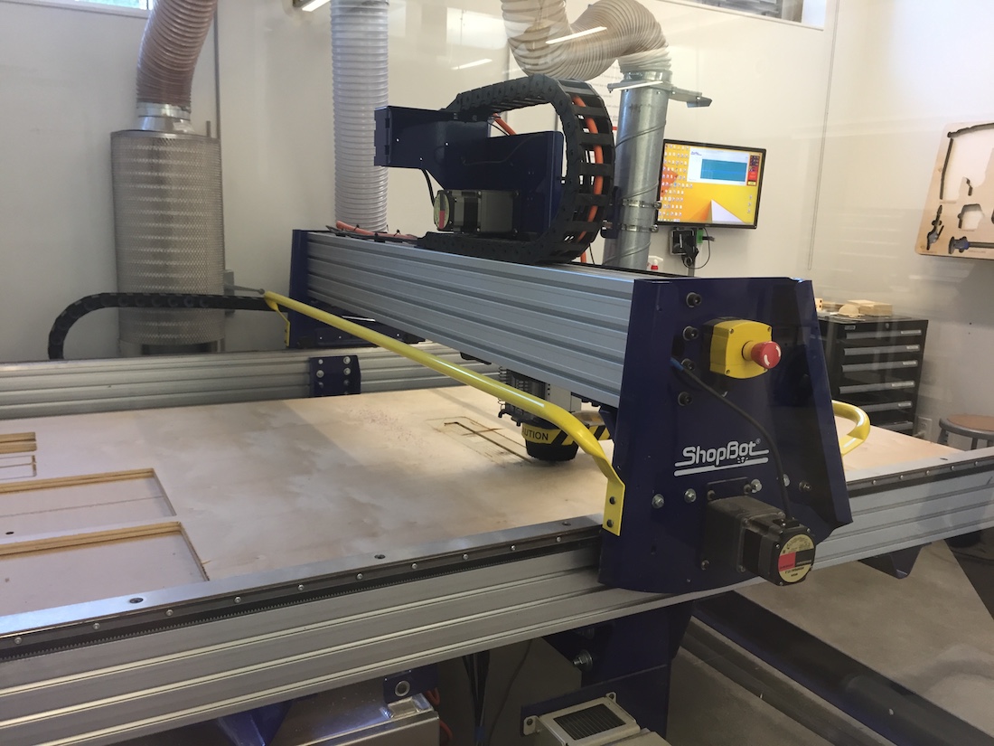
I designed the deck itself from scratch. This was an awesome excuse to get my hands dirty with a piece of fabrication equipment I had not gotten to interact with so far, the ShopBot CNC Router. This is an 8-foot by 6-foot behemoth of a CNC machine available to me in Jacobs Hall on campus at UC Berkeley. I modeled the splines of the deck after other off the shelf designs I had seen for longboards. I purchased an 8-foot by 6-foot piece of 3/4inch plywood for the project (it cost me $16) and was able to cut five decks out of it.
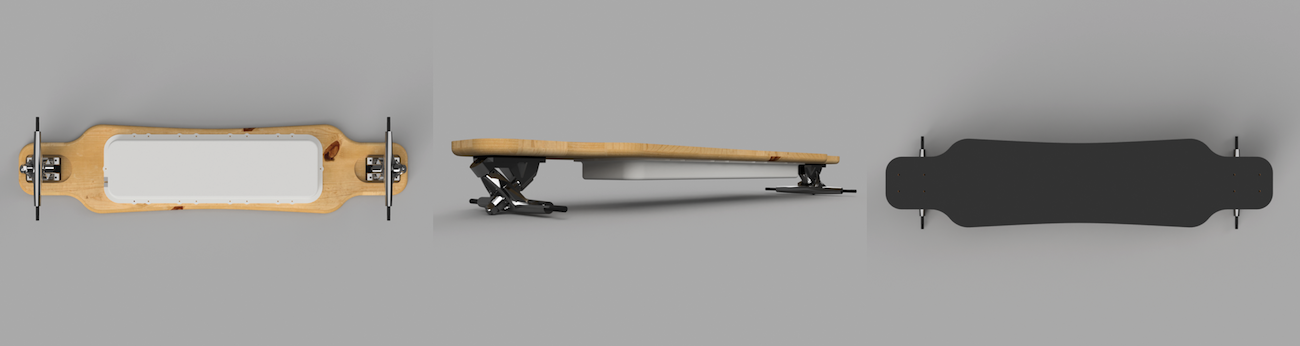
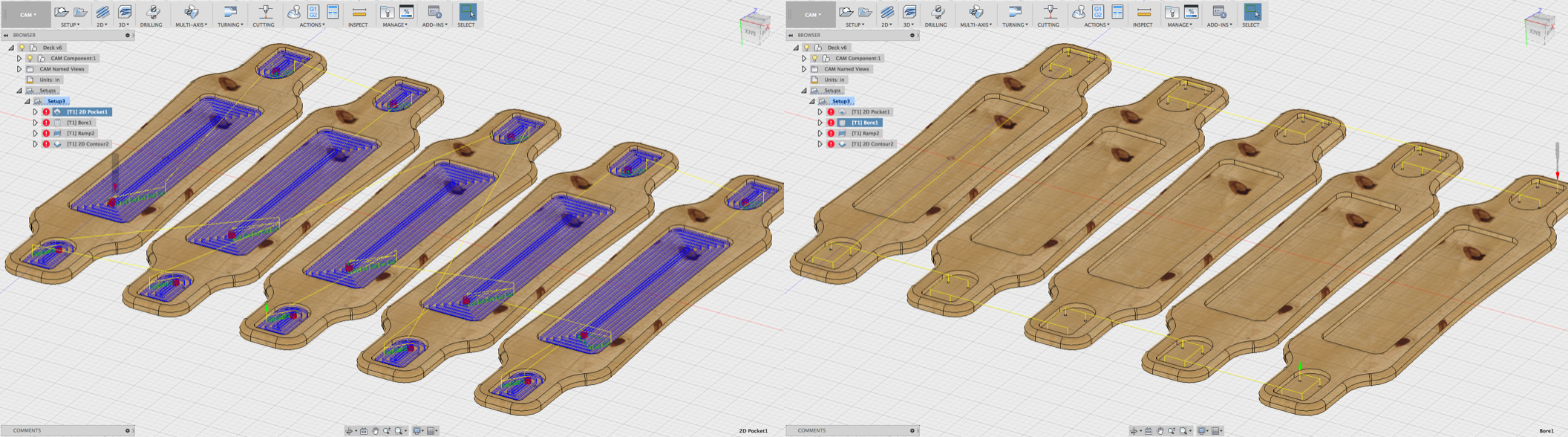
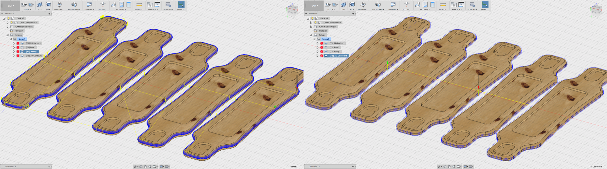
My design features a divot in the underside of the deck for low profile mounting of electronics, inset mounting for the trucks, and a filleted underside edge. It took 8 hours to cut all 5 decks using 4 tool changes on the ShopBot. This was also my first experiencing generating gcode for the ShopBot in Autodesk Fusion 360’s CAM workspace. The tool path simulations and automatic collision/interference warnings were super useful, and prevented me from destroying a CNC machine worth (much) more than my car. Here’s the tool paths outlined in Fusion:
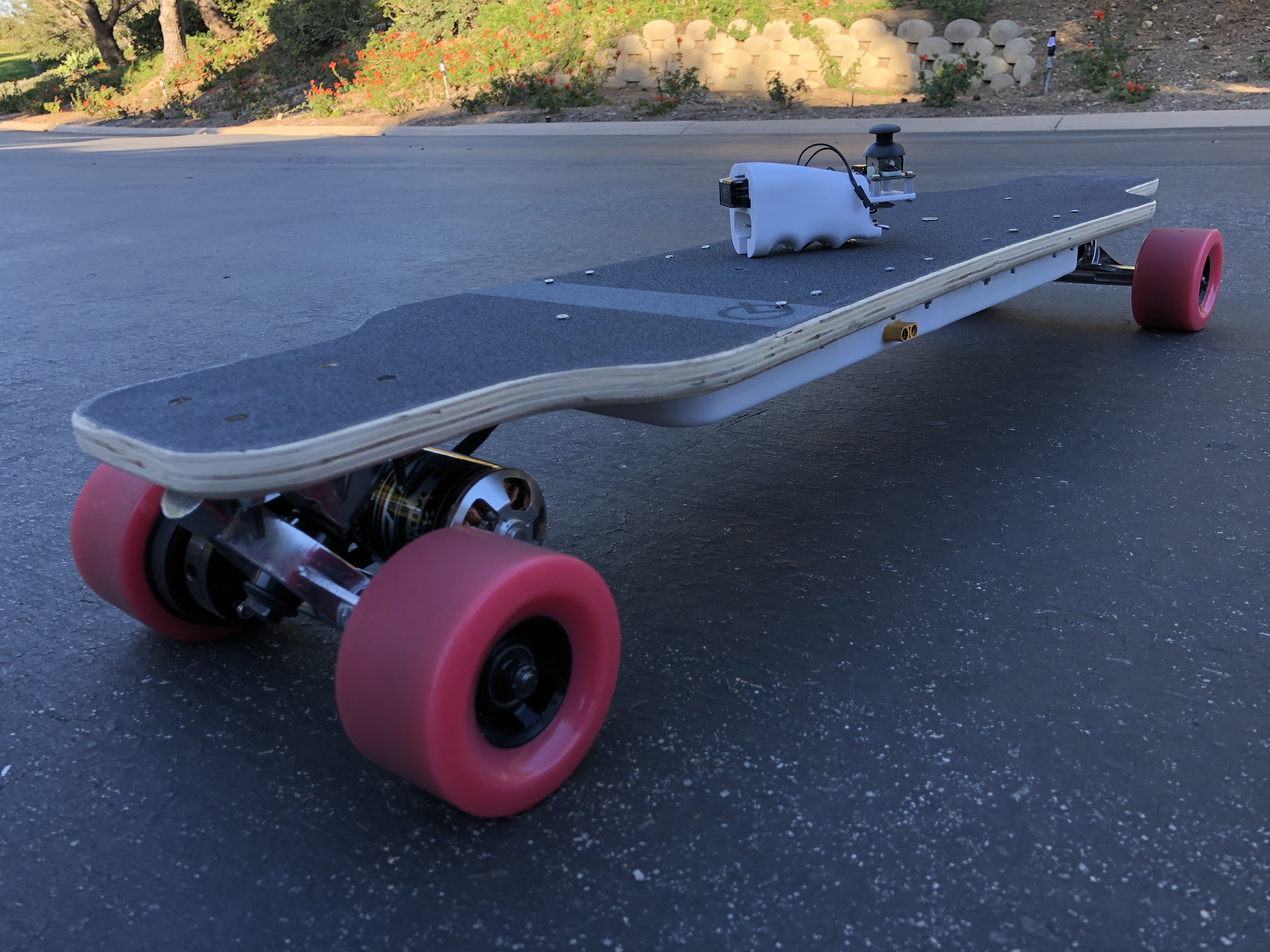
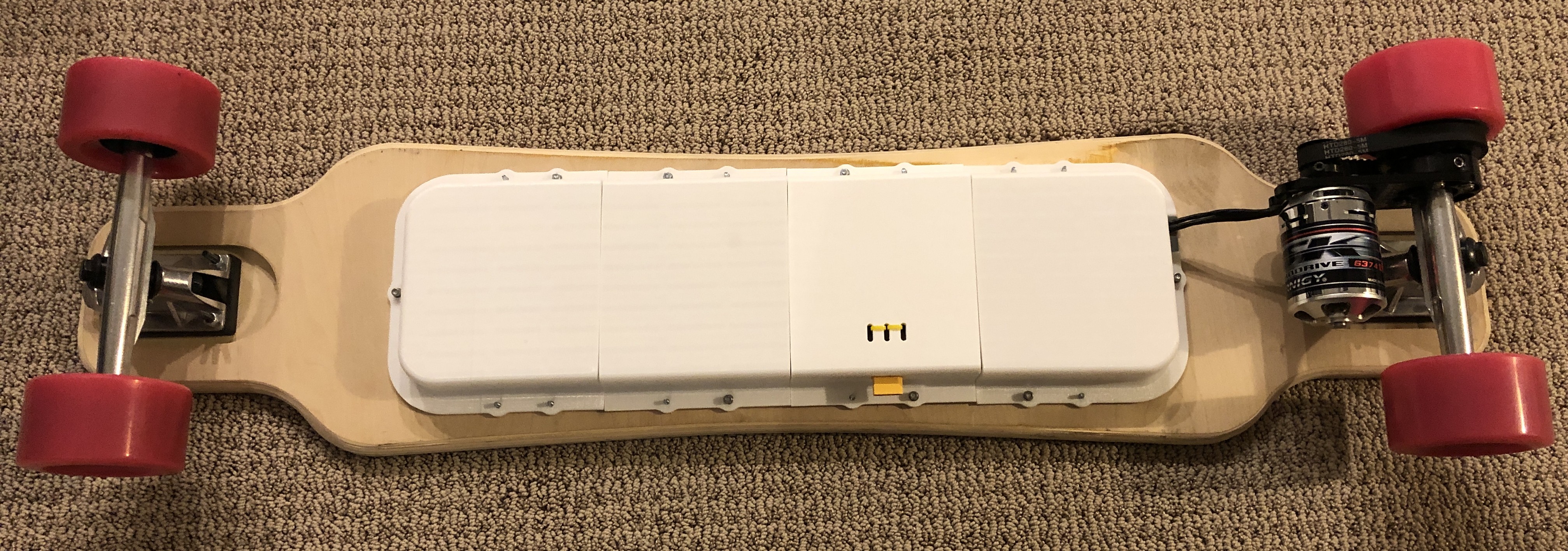
I designed and printed some enclosures which wrap over the divot in four pieces to protect the electronics bay from dust, debris, and water. They’re prototyped now out of PLA and are meant to be attached simply with M3 flathead screws. There’s opportunity for improving the serviceability of the board by implementing a latch or some other mechanism to access the batteries without unscrewing the lock nuts I’ve used. I’ve kept the design simple because the pieces are large and they take a long time to print, so iterating several times on a tightly toleranced mechanism was not a high priority. My printer can print PLA the fastest of any material and each of the four pieces still took 12 hours each. With a more capable printer, Nylon or PETG would be more suited materials for their greater flexibility and robustness to vibration and shock. Below is a picture of the board fully integrated with the enclosure attached.
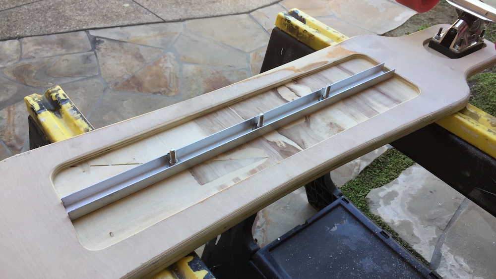
Longboards are typically made from bamboo, maple, birch, or composite materials. I made mine from a low-grade plywood without paying much attention to the load carrying capacity of my design. Upon hopping on for the first time, I felt an uneasy sinking at the center of the board under my weight rather than the springy feel of manufactured boards. I compensated with an aluminum beam spanning the electronics bay and it felt much safer.
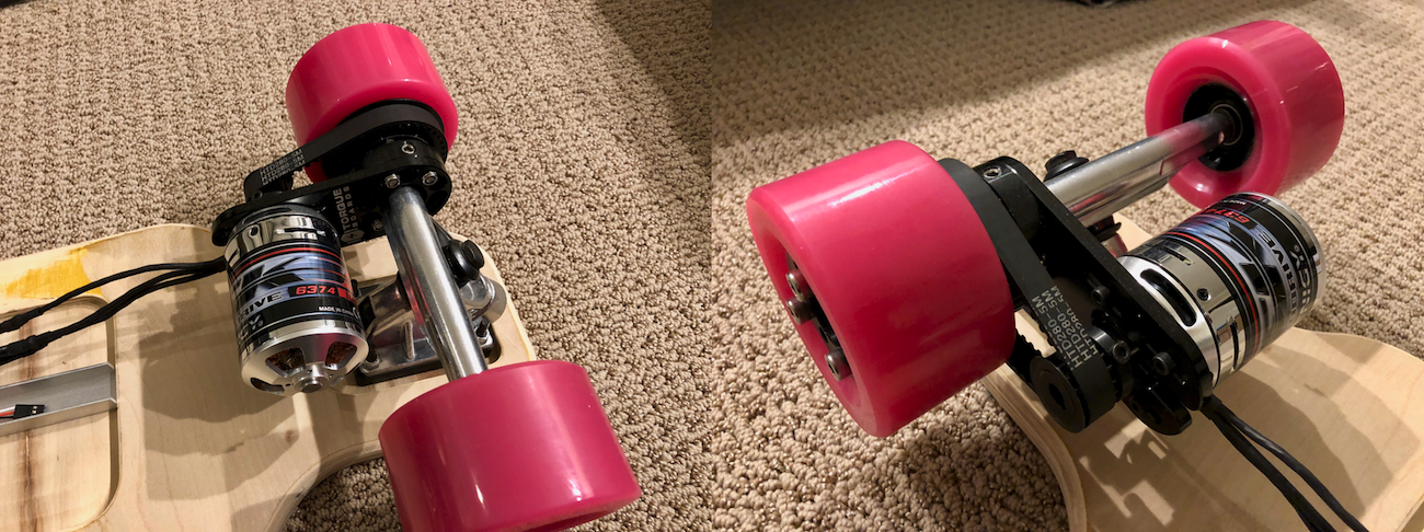
I sourced a few off the shelf parts from DIY Electric Skateboard for gears, pulleys, and a motor mount. This simplified the build, but I still had to modify my rear trucks meticulously with a file to mount the motor properly. Using the cast aluminum parts for the critical drivetrain components probably boosts my safety rating a bit.
The Handheld Remote
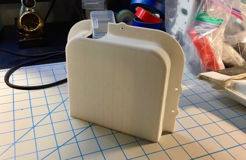
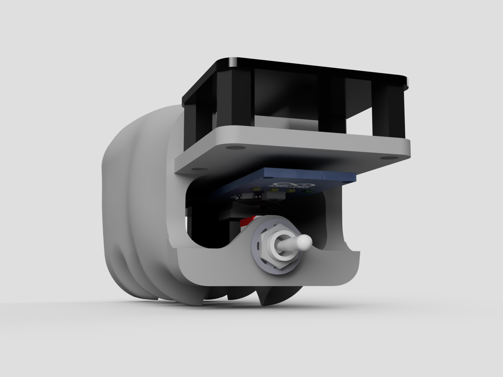
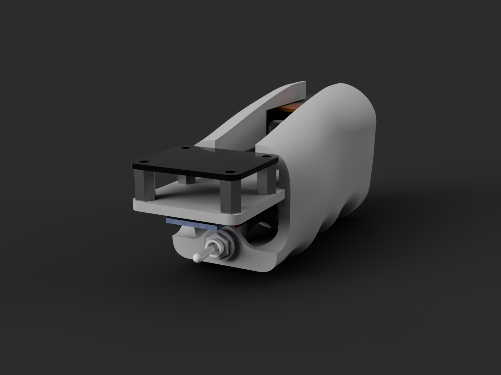
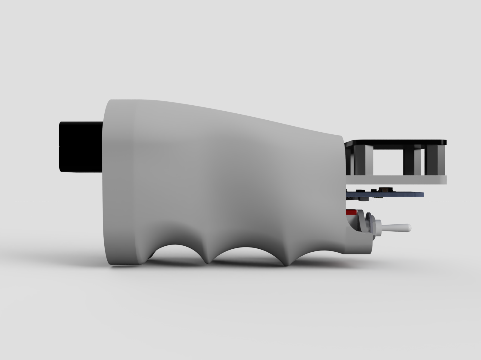
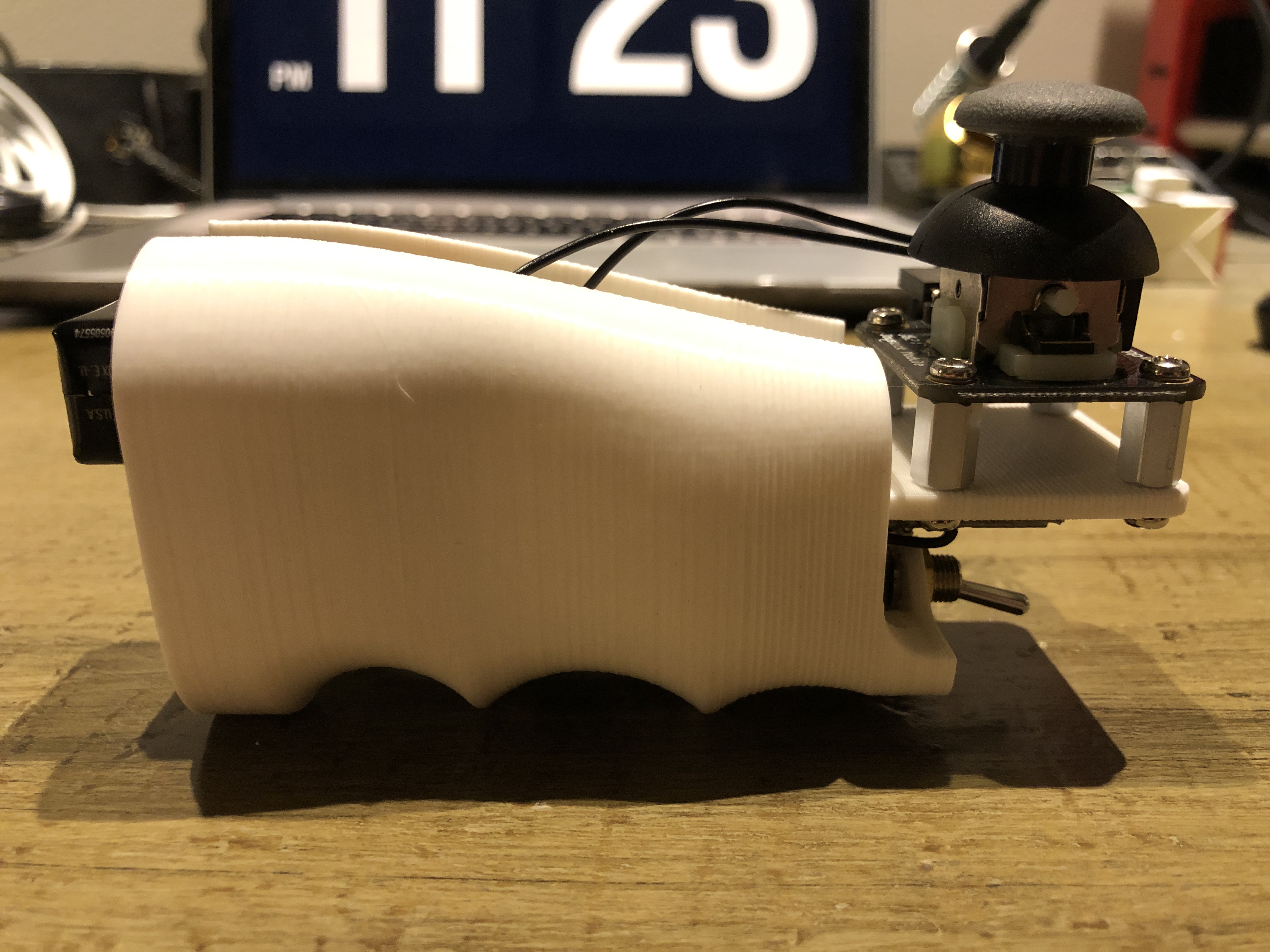
Inside the handheld wireless remote control, I had to fit an Arduino Nano, a 9V battery, an nRF24 transceiver module, an arming switch, and a joystick for throttle control. The arming switch is there to ensure a safe mode of “default” operation. The arming switch (also sometimes called a dead man’s switch) arms to motor so that control input is only acted upon while the momentary switch is being actively pressed. That way, if you drop the remote, or you fall off the longboard, it won’t zip away. In the mechanical design of the remote I was aiming for serviceability and access to the electronics as I was still testing the transceiver’s performance and tuning parameters in the transmitter’s software while the remote was put together. Ideally, the case would be relatively ergonomic and comfortable to hold as well. Ergonomics are certainly not my specialty, so I found open design files for a pistol grip online and modified it to mount the joystick and dead man’s switch, leaving a large open space for quick access to the electronics, which are held in place with industrial strength doubled-sided foam tape for now. Doubled-sided foam is quick, reliable, doesn’t leave a mess, and it’s not permanent so I use it all the side a temporary fastening method. Below are some renders of the remote and its physical incarnation after 3D printing the grip and integration of the electronics.
Software Design
The code for both the receiving (on the longboard itself) and transmitting (inside the remote) Arduinos is available in my GitHub repo for the longboard. My buddy David and I had plans that got canceled due to weather, so I roped him into the project and we hacked through all the Arduino code in a single afternoon.
The transmitting Arduino inside the remote takes of care:
- Reading the state of the joystick and arming switch
- Averaging a time series of the throttle input for smoother acceleration and braking
- Packaging the smoothed throttle output and arming switch state into a transmittable data structure
- Transmitting packets to the receiving nRF24 module
The receiving Arduino inside the electronics enclosure on the longboard is tasked with:
- Receiving packets from the transmitting nRF24 module
- Unpacking the data
- Generating a PWM throttle signal to send to the electronic speed controller (ESC) for the motor
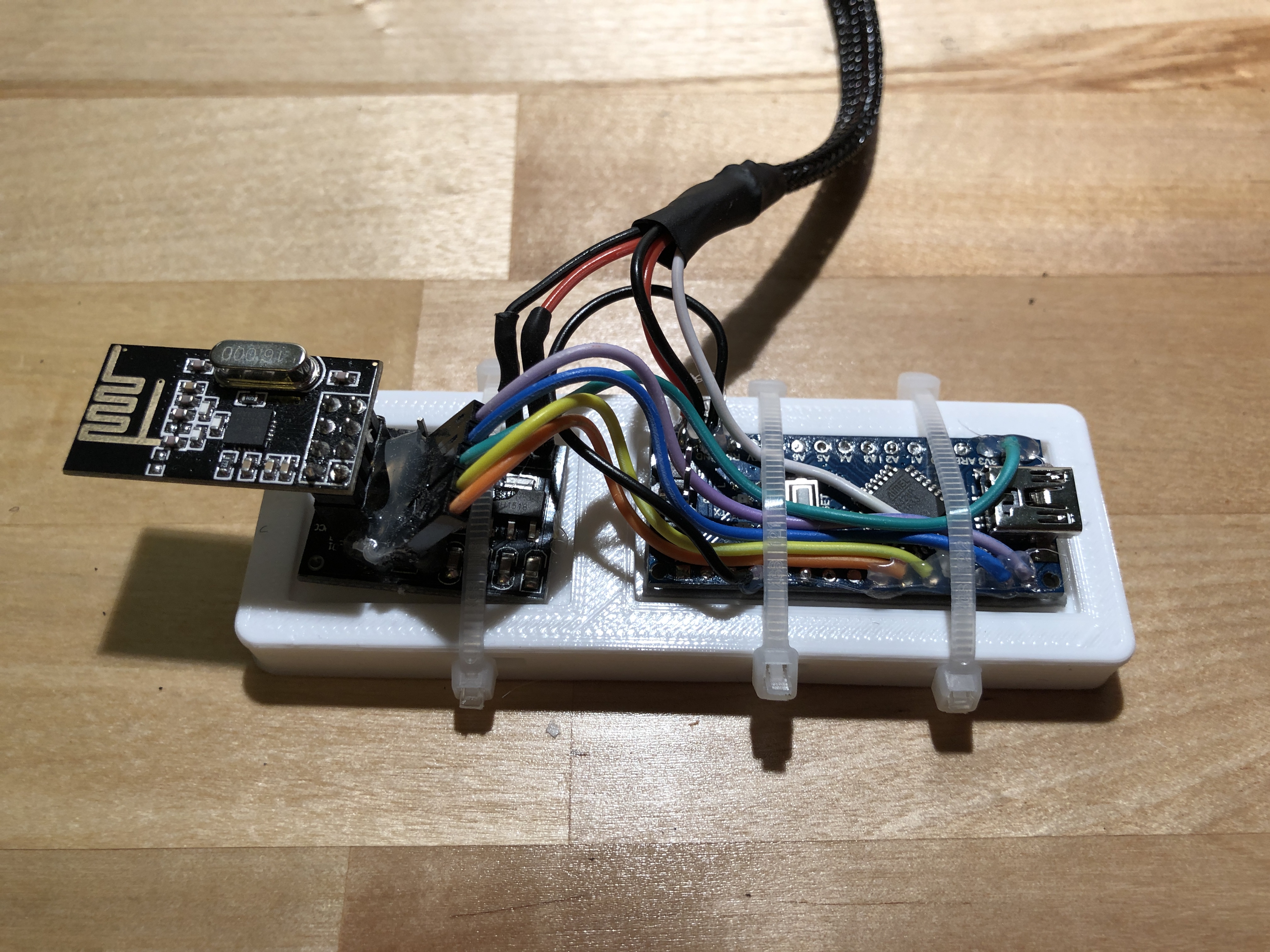
Below is the receiving side Arduino and its corresponding nRF24 module, the wire wrapped in braided nylon goes to the ESC. This 3D printed mounting solution is then secured to the underside of the board, inside the enclosure, using high strength velcro. I chose the Vedder ESC (VESC), an open-source hardware and software project which is purpose built for electric longboards and other high-power applications. The VESC includes a battery eliminator circuit which sends a clean 5V to the microcontroller to power it. The VESC simplified this project in a big way. It takes care of regenerative braking and runs the motor using a simple PID current controller. The motor back-EMF is characterized in the configurator that is distributed with the VESC’s firmware.
Testing
I tuned some of the ESC’s parameters in the BLDC Tool, a configurator for the the VESC’s firmware. I adjusted the PWM signal range, throttle deadband, and minimum duty cycle. I spun up the motor for the first time and tested the wireless controllers reliability. Upon confirming the implemented software failsafes (arming switch functionality, ESC behavior in case of a lost wireless connection, battery undervoltage, etc.), it was time to hop on.
The board delivered some excellent uphill acceleration and braking power shown in the video below. The remote control was easy to use on the board and the wireless connection never faltered. My only complaint so far is the occasional motor glitches at very slow speeds with high throttle setpoints. Providing data from a Hall effect sensor or visual motor encoder would allow the VESC to more accurately control slow speeds for smoother power delivery. I haven’t done any extensive testing to characterize the range or all out top speed yet. I need some more practice first, or some kneepads.