Crazyflie Flight Controls
A cascaded controller implementation for autonomous loitering with a Crazyflie quadcopter.
ME136: Introduction to Control of Unmanned Aerial Vehicles
I took this course in the Fall of 2017, my junior year. When I took it, it was a new class, the first time it had been offered at Berkeley, as well as the first ever class taught by a new faculty member Mark Mueller. I recognized Professor Mueller from ETH Zurich’s Institute for Dynamic Systems and Control, the birthplace of the PX4 project and online videos like this. I hadn’t taken any of the prerequisites for the class, but decided to go for it anyway. A number of UAVs@Berkeley personnel would be accompanying me and I assumed I could make up for a lack of prerequisite classes with my somewhat obsessive love for working on drones.
The class started with a seven week long deep dive into the dynamics of multirotors in the fully abstract tensor formalism. We started with aerodynamic models for propellers and ended with a mixer matrix, the basis for our attitude controller. While the lecture of the course focused on theory and analysis in dynamics, estimation, and control, the lab section focused on implementing a hover controller from scratch. The class was split into groups of 3 or 4 and each group was given a Crazyflie quadcopter to implement their controller.
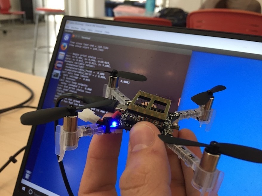
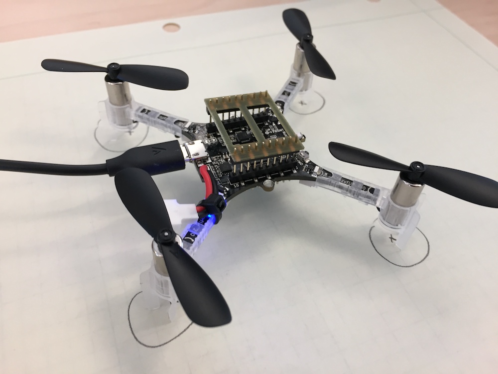
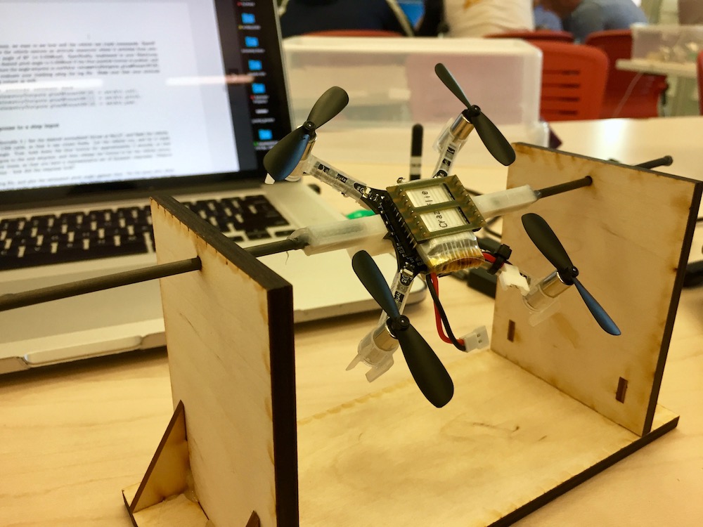
The Crazyflie is a tiny brushed quadcopter powered by a 1S LiPo. It has an STM32F4 microcontroller running NuttX. The PCB that the microcontroller sits on doubles as a rigid frame for the quadcopter. The hardware (mostly the motors) leave something to be desired, but the firmware interface was easy to work with. The class was given an Ubuntu virtual machine’s disk image to run in VirtualBox which had all the required dependencies installed. In the virtual machine, we compiled and flashed our custom firmware (all written in C++) to the board using the Eclipse IDE.
The final lab of the semester was a flight competition. Each group was pitted against each other to see who built the best performing controller. Long story short, we won, but more on that later. My lab group’s controller is available on my GitHub.
Course Description
This course introduces students to the control of unmanned aerial vehicles (UAVs). The course will cover modeling and dynamics of aerial vehicles, and common control strategies. Laboratory exercises allow students to apply knowledge on a real system, by programming a microcontroller to control a UAV.
- me.berkeley.edu
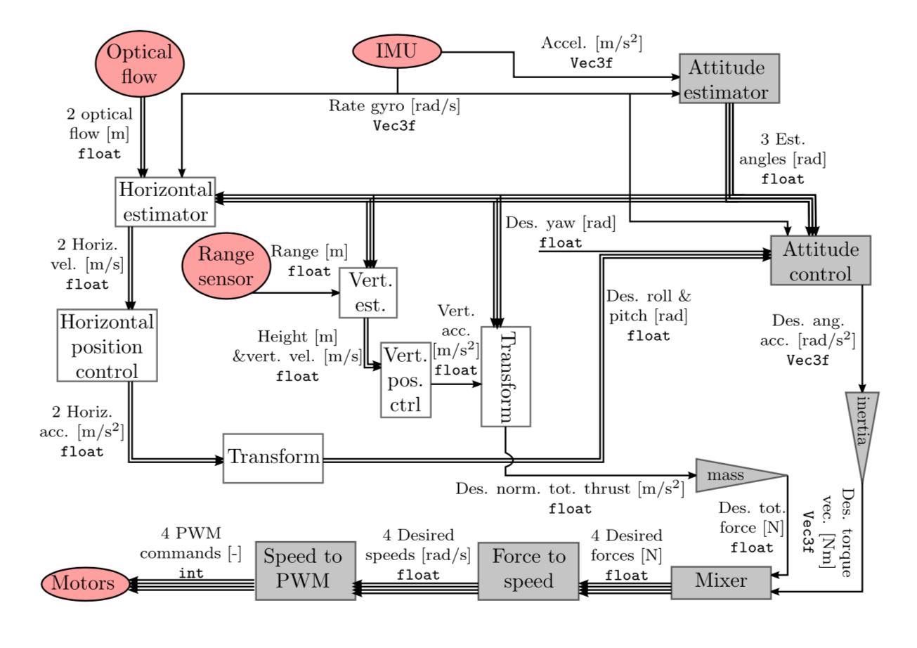
Full System Block Diagram
Here is the entire quadcopter controller represented in a block diagram as provided by our professor. Red ellipses represent hardware, shaded triangles represent simple summations and multiplications, and rectangles represent system parametrization and dynamics, or estimation and control algorithms we built up in lab sections.
Parameterizing the System
We started the lab section of the class by finding some scaling factors for the physical system empirically. Ultimately, we needed the transformation from the PWM command we could dictate as an output of our control, to the thrust produced the motor. The thrust produced at each motor creates a moment about the vehicle’s center of mass and contributes to the total normalized thrust. We find this transformation in two steps:
Motor PWM to Propeller Angular Velocity
We needed to know how PWM commands from the flight controller to the motors affect the angular velocity of the propellers. We took a photo laser tachometer and measured the propeller RPMs at various PWM commands and derived a linear relationship.
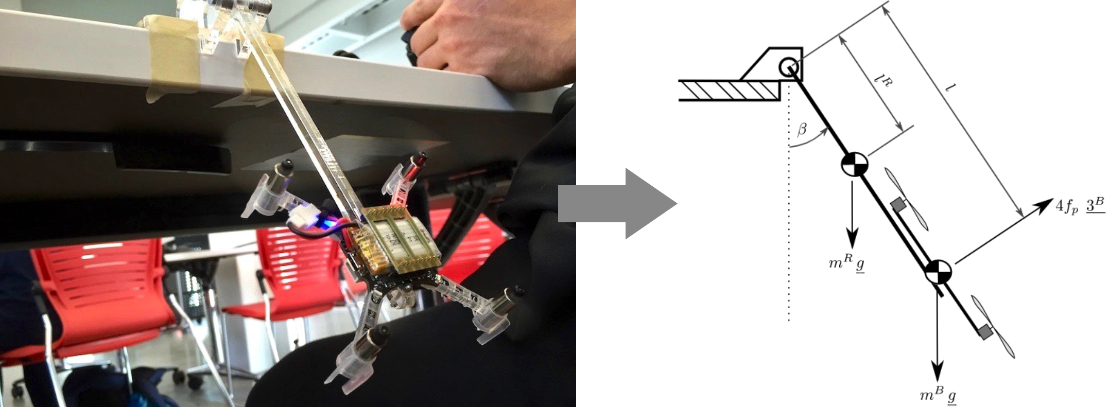
Propeller Angular Velocity to Thrust
The class didn’t have any thrust stands available, so the GSIs got creative and gave each team a lever made from laser cut acrylic that the Crazyflie could be fastened to with M2 screws. The lever was fixed to the edge of a table with tape. We commanded various propeller angular velocities (using our new PWM to angular velocity relationship) and logged the accelerometer data to find the average angle that the quadcopter arrived at. Then we solved the statics problem embodied by the free body diagram to determine the thrust force that each propeller was producing. We derived a quadratic relationship here.
State Estimation
Attitude Estimator
The attitude estimator obtains the orientation of the quadcopter (pitch, roll, yaw) in the body frame of the vehicle. It uses the sensor data from the IMU (a rate gyroscope and an accelerometer). We parametrized the rotations (a frighteningly rich topic that I was not aware of before taking this class) of the vehicle using Euler angles. I recognize that this choice makes us look like we’ve learned nothing from Apollo 11. We implemented rotations using Euler angles because they are intuitive and easy to visualize, but they do suffer from singularities (gimbal lock, wrist flip, etc. depending on who you talk to), and some computational slowness. This was acceptable since we were looking to control about a hover, if our quadcopter passed through 90 degrees in pitch, something bad happened. Quaternions of rotation (not the hypercomplex ‘Quaternions’), are the best choice for rotation parametrization because they do not suffer from singularities and are not computationally intensive. Quaternion parametrization was introduced at the end of the class, and redoing our entire attitude estimator using quaternions in the week before the class competition seemed unwise.
Here’s the estimator as it was originally designed in lab, notice we use a trade-off factor p = 0.01 so we heavily favor the gyroscope, but supplement it with the accelerometer data to prevent drift.
//***Gyro + accelerometer attitude estimator***
estRoll = (1.0f-p)*(estRoll + dt*rateGyro_corr.x) + p*(in.imuMeasurement.accelerometer.y / gravity);
estPitch = (1.0f-p)*(estPitch + dt*rateGyro_corr.y) + p*(in.imuMeasurement.accelerometer.x / -gravity);
estYaw = estYaw + dt*rateGyro_corr.z;
In preparation for the final competition we decided to eliminate the small angle approximations, sacrificing ease of computation for a more accurate estimator. It improved performance and stability in some scenarios.
// ***Gyro + accelerometer attitude estimator + no small angle approximations***
AngVel.x = rateGyro_corr.x + rateGyro_corr.y*(sinf(estRoll)*tanf(estPitch)) + rateGyro_corr.z*(cosf(estRoll)*tanf(estPitch));
AngVel.y = rateGyro_corr.y*cosf(estRoll) - rateGyro_corr.z*sinf(estRoll);
AngVel.z = rateGyro_corr.y*((sinf(estRoll))/(cosf(estPitch))) + rateGyro_corr.z*((cosf(estRoll))/(cosf(estPitch)));

// beware accelerometer and gyro measurements on different axis can reflect the same motion
estRoll = (1.0f-p)*(estRoll + dt*AngVel.x) + p*(asinf( in.imuMeasurement.accelerometer.y / (gravity*cosf(estPitch))));
estPitch = (1.0f-p)*(estPitch + dt*AngVel.y) + p*(asinf( in.imuMeasurement.accelerometer.x / -gravity));
estYaw = estYaw + dt*AngVel.z;
Height Estimator
The height estimator relies only on a range sensor below the quadcopter. This is a noisy sensor, so we’ve implemented some checks to throw out bad data. It’s also a slow sensor so it doesn’t update at every call to our main loop. The one subtlety in working with this sensor is that a change in pitch or roll angle will cause the detected distance to the ground to change. We account for this in hMeas, and mix this value with estHieght which updates with an estimated velocity based on the height deltas between successive calls to the main loop.
// height estimator:
// prediction step:
estHeight = estHeight + estVelocity_3 * dt;

// correction step, directly after the prediction step:
float const mixHeight = 0.3f;
if (in.heightSensor.updated) {

	// check that the measurement is reasonable
	if (in.heightSensor.value < 2.0f) {
		float hMeas = in.heightSensor.value * cosf(estRoll) * cosf(estPitch);
		estHeight = (1 - mixHeight) * estHeight + mixHeight * hMeas;

		float v3Meas = (hMeas - lastHeightMeas_meas) / (in.currentTime - lastHeightMeas_time);

		estVelocity_3 = (1- mixHeight) * estVelocity_3 + mixHeight * v3Meas;
		// store this measurement for the next velocity update
		lastHeightMeas_meas = hMeas;
		lastHeightMeas_time = in.currentTime;
	}
}
Horizontal Estimator
The horizontal estimator is very similar to the height estimator in that we must account for pitch and roll changes past some small angle. We augment the optical flow sensor outputs sigma_1, sigma_2 with rate gyro data in pitch and roll. Note here that optical flow only gives us information on horizontal velocity (hence “flow”) so we’ve got to integrate to get an estimated position.
float const mixHorizVel = 0.5f;
if (in.opticalFlowSensor.updated) {
	float sigma_1 = -in.opticalFlowSensor.value_x;
	float sigma_2 = -in.opticalFlowSensor.value_y;

	float div = (cosf(estRoll) * cosf(estPitch));

	if (div > 0.5f) {
		float deltaPredict = estHeight / div;

		float v1Meas = (-sigma_1 + in.imuMeasurement.rateGyro.y) * deltaPredict;
		float v2Meas = (-sigma_2 - in.imuMeasurement.rateGyro.x) * deltaPredict;

		estVelocity_1 = (1.0f - mixHorizVel) * estVelocity_1 + mixHorizVel * v1Meas;
		estVelocity_2 = (1.0f - mixHorizVel) * estVelocity_2 + mixHorizVel * v2Meas;
	}
}

estPos_1 = estPos_1 + (dt * estVelocity_1);
estPos_2 = estPos_2 + (dt * estVelocity_2);
Controller
I struggle with how to talk about the controller on my website in just a few paragraphs. I feel like I’d have to write a few thousand words to offer any more insight than the source code alone can provide. If staring at the source code interests you, then by all means check it out. Basically, the controller takes our state estimation to be truth and controls around a flat, zero-velocity state for the quadcopter, i.e. hovering at about half a meter off the ground. The approach is cascaded (so rate control is more aggressive than angle control for example) and time constants are chosen so that nested controllers at each stage can be considered instantaneous.
Flight Competition
The last lab section of the course was a hovering contest among the 20 or so lab groups. A net was set up in the middle of the room, enclosing a 6ft by 8ft rectangular prism, about 8ft high. You could place your quadcopter on the ground anywhere inside the netting but then you had to pass your XBox controller off to a GSI who would press the red button to start your main loop and begin your autonomous hover (hopefully). Each team was given 8 minutes to run as many flights as possible, the longest flight wins! Our actual lab grade depended on how we ranked against the other teams, so the stakes were high. There was one catch: after 90 seconds of flight, one of the GSIs would turn on a fan inside the netting to destabilize the controller or blow the quad into a net.
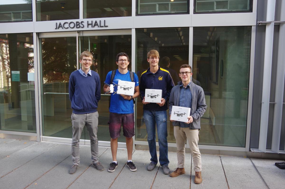
My team (David, Joey, and I) was the only team to reach 90 seconds of flight and have the fan turn on. On our longest run we achieved 105 seconds of flight before crashing into the net, withstanding the fan for 15 seconds. We were excited, I wish I had video of the event, but we had pulled an all-nighter before the competition tuning and perfecting the controller and it slipped my barely functional mind at the time. There were many modifications we made to the stock controller which allowed us to achieve this performance. We eliminated small angle approximations from our estimators and controllers, we implemented position control as well as an absition feedforward (the integral of position is called “absition” or “absement,” it’s a thing). We added height setpoint scheduling for a smooth takeoff as well as hard-coded gain scheduling on the attitude controller. These changes, along with fine tuning our time constants through many hours of flight tests, allowed us to stay in the air for longer than we expected. Kitty Hawk ended up sponsoring the competition with a DJI Spark drone for each member of the winning team. Here we are on zero hours of sleep, but very gratified. Left to right Professor Mueller, David, Joey, and yours truly.
ME136 was a challenge but cemented my interest in controls. Of all the all-nighters I’ve pulled, the one before this class competition was one of the most worthwhile.